Ausmini
It is currently Sun Apr 28, 2024 4:17 pm

All times are UTC + 10 hours


Post new topic Reply to topic  [ 46 posts ]  Go to page 1, 2, 3, 4  Next
Author Message
 Post subject: Hydrolastosity
PostPosted: Wed Nov 27, 2013 9:00 am 
Offline
Hydrolastosity

Joined: Fri Sep 27, 2013 7:52 am
Posts: 25
Location: a Ville in the Forest, NSW
Hello all,

First, I would like to introduce myself, my name is Don Welch…I bet you'd never of guessed! My wife and I picked up a '67 Morris Cooper S earlier this year and I've been rebuilding it since. It was last registered in '83 and has been sitting ever since (as the story goes). Pulled the motor after a fresh rebuild because the diff bearing cages let go and never found the time to get it back on the road. Which is a good thing, as the car has been smashed in the rear, right rear quarter replaced (badly), along with several other issues that fall in line with his favorite saying "its what you did when you were 18".

Secondly, I would like to say thank you to many of you on the board, both those I've contacted for questions or parts, and those who've contributed to the posts I've been reading for the past 6+ months. Lurking and learning, edumicating myself on these cars that I've loved my whole life.

This car has been a big project, and some major headaches. But this is what I wanted, to learn something new and put my skills to use. I'm a first class metal machinist by trade, (lathe, mill, CNC programming, CAD drawing), welding (TIG and oxy acetylene), to fabrication of racing parts including oil tanks, brake adapters, drivetrain parts, roll cages, etc. Automotive wise, I have just over 10 years experience working on air cooled Porsches, mainly 911's and 914's. Rebuilding engines and transmissions, suspensions and auto body repair (panel repair, replacing, and painting).

Back to the mini, first thing was cleaning, inspecting, research, and rebuilding all parts. One of the hard lines needed to be patched, so I silver soldered a piece over the corroded area, then silver zinc plated both lines. The bags were cleaned out with methylated spirits to attempt to get all water and rust grime out, then blasted and painted. Each bag was pressure tested to 350psi nitrogen for 24 hours.

Image

Image

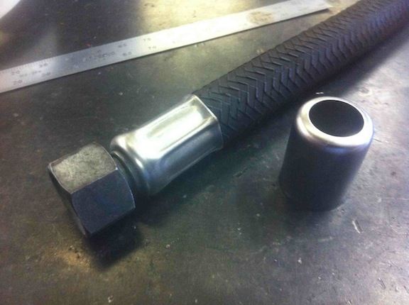
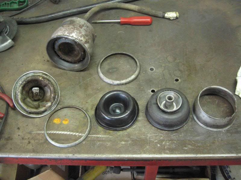
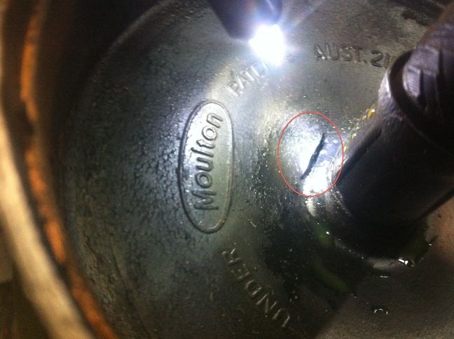
One of the bags' flexible line was damaged, so I set out to research what hose is available to replace this. I have not found anything as of yet that looks identical. The hose above is scrap from the bag I cut apart. The main problem is the crimped ferrule below the bag mounting rim… So I set out to solve this.

Image

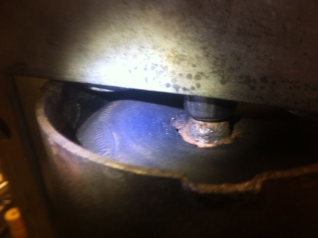
This is the same as the above picture with bag under nitrogen pressure. The crimp looks different (not flared at the top) because its wrong as I was working on the depth settings for the tool I made. It has been re-done (stupidly I did not get a photo of it), and it has been holding 250psi fluid pressure in my car for two weeks now. True test is yet to come...

Image

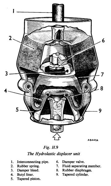
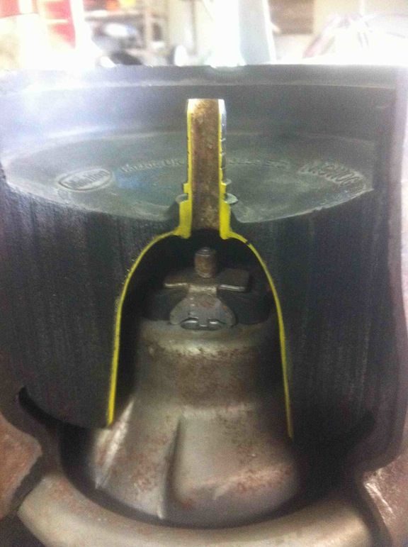
Another bag, which was a rear bag, had badly rusted around the bladder skirt (known as a Tapered cylinder #9 in the above cut away drawing). I was told this was black rust and should not risk using this bag. This was my chance to confirm the drawing, possible reverse engineer as well as do a few tests along the way. Using a spring rate tester, the inner vulcanized rubber spring is about 5000lb/in. I'm toying with the idea of making my own hydrolastic bags out of aluminium, interchangeable rubber springs for different rates, and serviceable for re-valving the internal hydro workings. I don't imagine there is much of a market, as most of the cars still running hydrolastic are doing so because they are collectables that came that way.

Cut away, yellow showing inner steel bell vulcanized to rubber spring.
Image

Image

I'm also working on a tool that will allow me to open up these bags, so the internals can be properly cleaned, inspected, and or repaired. Then re-crimped so it looks like I was never there. Wishful thinking at this time, but time will tell.

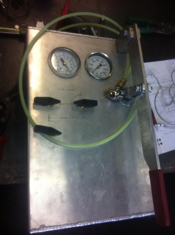
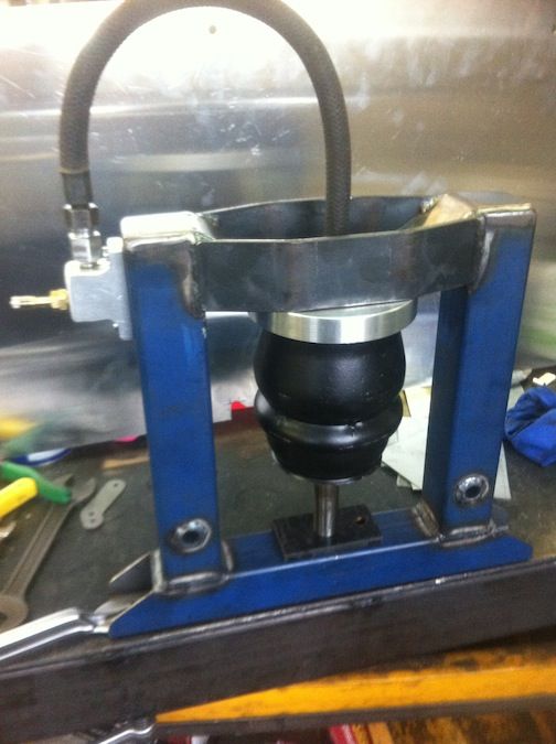
I've made a hydrolastic pump that can pressurize at least 400psi and pull 20+" Hg vacuum, along with a jig to hold the hydrolastic bags and test them at pressure. I'm also making an electric motor driven cam/roller system that will bump the bag under pressure to depict road driving. These can be tested, even though there realistically cannot be a guarantee associated, there can at least be some reassurance that they will hold a standardized test. Especially considering how much of a pain these are to get in and out of the car.

Image

Image

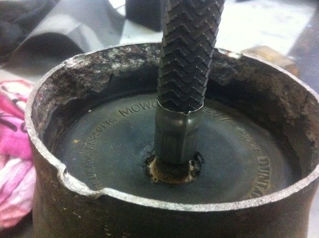
Now that this suspension and parts are reaching rare/unobtainium status, I encourage anyone who owns a business or has personal spare hydrolastic bags, please pull them out, flush them with methylated spirits, fill them with cheap coolant or another corrosion preventative fluid, and cap them. The saying "Worked when removed from car" is no longer comforting. I recently purchased a second hand bag, pressure tested it with nitrogen to 350psi and all was good. As soon as I put it in the car and pumped to 250psi fluid, within 3 minutes it ruptured through the rubber section. This can only be the result of the internal steel bell (yellow outline in the above cut-away) has rusted enough to break. Once you drain these bags, oxygen can enter and is the main contributor to oxidation… ie: rust. Even if you cannot be bothered to clean them, fill them and seal them. I will try to come up with several cheap ideas of sealing these, or even make some cheap caps it there is enough interest.

Rupture
Image


Thank you for you time, Don.


Last edited by Don Welch on Thu Nov 28, 2013 6:03 am, edited 1 time in total.

Top
 Profile  
 
 Post subject: Re: Hydrolastosity
PostPosted: Wed Nov 27, 2013 10:47 am 
Offline
848cc
848cc

Joined: Tue Sep 03, 2013 4:22 pm
Posts: 63
Location: Sydney
Impressive dedication Don to the preservation of the hydrolastics... I have 3 spare bags, and will be giving them a clean and fill with coolant this weekend.

Might be worth listing your location as well, cheers.

Geoff


Top
 Profile  
 
 Post subject: Re: Hydrolastosity
PostPosted: Wed Nov 27, 2013 11:37 am 
Offline
1360cc
1360cc
User avatar

Joined: Wed Oct 03, 2007 9:04 pm
Posts: 6654
Location: Melbourne, VIC
Hi Don,

A warm welcome to Ausmini. If the quality of your post is anything to go by you will be a real asset to the forum. You may have noticed there are forum members who participate in various ways. Some like to chat to other like-minded Mini enthusiasts on a semi-social basis, whilst others are mainly here to give and receive technical information and increase their knowledge of this fascinating little vehicle. I put myself in the latter category. Many very knowledgeable members don't post often but they watch what's happening so feel free to ask questions, and also continue to share your experiences.

Be aware that, with posts like the one above, you may end up being the resident displacer expert. :wink: Of course the Doc probably holds that mantle currently as you will have seen if you searched old threads on the topic. Until the forum search function is fully operational I suggest you use Google to search the forum. Start with the search term site:ausmini.com and then add search topic keywords as needed.

I have an unmolested 1970 MK II Cooper S that's about to be restored so your information on displacer preservation and restoration is very relevant. One displacer was replaced by the previous owner because the rubber hose was punctured so I'm very interested in techniques to repair it. Did you find a source for the original style hose?

Given your technical background I thought you might be interested in seeing the BMC Australia engineering drawing for displacers (below). You are no doubt aware of the drawing office codes for various vehicles - YDO5 is the standard hydrolastic Mini (Deluxe, Matic, K) and YDO 6 is the Cooper S. You'll see from the drawing that standard Minis had the same displacer type front and back whilst the Cooper S had different displacers for front and back.

Can you explain to me the damping characteristics (see the table) in layman's terms and how that relates to flap valve K420 and K650? It's probably contained in a technical document somewhere but maybe you can provide a simple explanation.

So welcome aboard. I hope you have the ride of your life. :D

P.S. Whilst not mandatory it would be good if you could show your location in your signature.

Image

_________________
ex-NSW Police 1970 MK II Cooper S
VMCI #43


Top
 Profile  
 
 Post subject: Re: Hydrolastosity
PostPosted: Wed Nov 27, 2013 1:01 pm 
Offline
Hydrolastosity

Joined: Fri Sep 27, 2013 7:52 am
Posts: 25
Location: a Ville in the Forest, NSW
Thanks guys, missed that... location added. I live northern beaches way and work at Sydney Shock Absorbers near Sydney airport... its meer ironic that I work for a shock absorber company and am repairing this old system, but its so unique that its worth it to me, and hopefully others. I will try to do my best to provide explanations of what I've learned thus far. Thanks for the drawing too!

I have not found hose that looks identical to the original. I do not believe we will find another hose with the same rubber woven look and performance numbers unless someone contracts a tubing company to make it. I have however used a german hose manufacture in past for oil and fuel line rebuilding and manufacturing. They have a hose that has a working pressure of 50bar, test pressure of 75bar, and a burst pressure of 170bar... all with the same internal and external dimensions as the original, ferrules are gold zinc plated. All specs I've seen for pumping up a mini is just less than 300psi (20bar). They make other lines that have fabric woven exterior which look nice, but the working pressures are about 10bar, test 20bar, and burst 30bar. I'm not sure I want the burst to be that close to what our working pressures will be. They do have a stainless braided line that works 32bar, tests 48 and bursts 80... maybe for the bling bling bags perhaps?

The valving is most likely changed by the size of the bound and rebound rubbers and/or pressure of the crimp that holds them to the valve body (this is an assumption as I haven't opened any other bag or tested the bag I have yet for the valve rate... I have plans to make a tool to test this part of the bag).

Topside of valve body. Low speed (small bumps) valve hole lower and bump valve (big bumps) in rubber
Image

Underside of the valve body. Low speed hole and rebound valve in rubber
Image

This is the same basic design as most shock absorbers, except oil shocks use different diameter and thickness washers to achieve different rates of fluid dampening (as well as pressure within the system). We can get knee deep in this, but I hope this helps your question?

Cheers, Don


Last edited by Don Welch on Wed Nov 27, 2013 1:16 pm, edited 1 time in total.

Top
 Profile  
 
 Post subject: Re: Hydrolastosity
PostPosted: Wed Nov 27, 2013 1:15 pm 
Offline
Hydrolastosity

Joined: Fri Sep 27, 2013 7:52 am
Posts: 25
Location: a Ville in the Forest, NSW
...any way of getting a better resolution of that technical drawing? I can sorta make out the numbers. The testing speeds, bump and rebound I'm familiar with and can replicate with the shock dyno we have. looks like 60+/- 25% @10 and 285+/-10% @100 etc...

I'm not opposed to testing bags at working pressures for people or businesses. I can also build tools if there is interest. Haven't thought about it much as I'm still building and testing everything I've done thus far.


Top
 Profile  
 
 Post subject: Re: Hydrolastosity
PostPosted: Wed Nov 27, 2013 1:46 pm 
Offline
1360cc
1360cc
User avatar

Joined: Wed Oct 03, 2007 9:04 pm
Posts: 6654
Location: Melbourne, VIC
Don,

The Doc has also looked for a replacement hose supplier but without luck to date.

There's sometimes debate over the markings on hydrolastic units so I've posted below some hand-written information (dated September 1972) attached to the displacer drawing.

In terms of pressure the following narrative is from the factory Mini Suspension Trimming Data specification - drawing AYG4120.

INITIAL PRODUCTION (where 4 new hydrolastic units are used).

1. Evacuate to not less than 28 inches of mercury.
2. Overcharge to 400 (+/- 30) p.s.i. for 60 minutes minimum.
3. Relieve pressure to 275/285 p.s.i. to give front trim height of 13.5 / 14.0 inches with vehicle in a fully completed unladen state with one gallon of fuel in the tank but no tool kit. This trim height is above specification to allow for initial sag of hydrolastic units.

SERVICE

1. Evacuate to not less than 27 inches of mercury.
2. For new spring units only, overcharge to 350 (+/- 20) p.s.i. for 60 minutes minimum.
3. Pressurise to give a front trim height of 13.0 / 13.5 inches with vehicle in a fully completed unladen state with five gallons of fuel in the tank (pressure will be in the range 260/285 p.s.i.).

A differential in pressure side to side may be used to equalise trim heights on each side of vehicle.

Vehicle must not be run at pressures exceeding 290 p.s.i.

Trim height to be measured vertically from hub centre to wing beading.


Image

_________________
ex-NSW Police 1970 MK II Cooper S
VMCI #43


Top
 Profile  
 
 Post subject: Re: Hydrolastosity
PostPosted: Wed Nov 27, 2013 2:05 pm 
Offline
1360cc
1360cc
User avatar

Joined: Wed Oct 03, 2007 9:04 pm
Posts: 6654
Location: Melbourne, VIC
Don Welch wrote:
...any way of getting a better resolution of that technical drawing?


ImageImage

_________________
ex-NSW Police 1970 MK II Cooper S
VMCI #43


Top
 Profile  
 
 Post subject: Re: Hydrolastosity
PostPosted: Wed Nov 27, 2013 3:32 pm 
Offline
Hydrolastosity

Joined: Fri Sep 27, 2013 7:52 am
Posts: 25
Location: a Ville in the Forest, NSW
Oh ya... now we're cookin with gas! This is great, now we have a base point once I get my act together and make a jig for testing.


Top
 Profile  
 
 Post subject: Re: Hydrolastosity
PostPosted: Wed Nov 27, 2013 3:39 pm 
Offline
1098cc
1098cc
User avatar

Joined: Wed Aug 04, 2004 6:21 am
Posts: 1788
Location: Wullingtun, Unzud
This is one of the reasons I love the internets.

Can I suggest a moderator changes you from 'n00b' to 'Mr Moulton'?

Off to check the state of my stored hydro bags...


Top
 Profile  
 
 Post subject: Re: Hydrolastosity
PostPosted: Wed Nov 27, 2013 3:41 pm 
Offline
religious status
religious status
User avatar

Joined: Fri Mar 19, 2004 6:19 pm
Posts: 39643
Location: near Baulkham Hills, NSW
I am watching this with interest... 8)

_________________
DrMini- 1970 wasaMatic 1360, Mk1S crank, 86.6HP (ATW) =~125 @ crank, 45 Dellorto (38 chokes), RE282 sprint cam, 1.5 rockers, 11.0:1 C/R. :mrgreen:


Top
 Profile  
 
 Post subject: Re: Hydrolastosity
PostPosted: Wed Nov 27, 2013 4:30 pm 
Offline
1360cc
1360cc
User avatar

Joined: Wed Oct 03, 2007 9:04 pm
Posts: 6654
Location: Melbourne, VIC
Don - when I refer to Doc I am talking about drmini in aust who has just posted.

_________________
ex-NSW Police 1970 MK II Cooper S
VMCI #43


Top
 Profile  
 
 Post subject: Re: Hydrolastosity
PostPosted: Wed Nov 27, 2013 4:40 pm 
Offline
Hydrolastosity

Joined: Fri Sep 27, 2013 7:52 am
Posts: 25
Location: a Ville in the Forest, NSW
winabbey wrote:
Don - when I refer to Doc I am talking about drmini in aust who has just posted.


Ya, I've been lurking for some time and picked up on that pretty quick. Cheers, d 8)


Top
 Profile  
 
 Post subject: Re: Hydrolastosity
PostPosted: Wed Nov 27, 2013 6:05 pm 
Offline
Hydrolastosity

Joined: Fri Sep 27, 2013 7:52 am
Posts: 25
Location: a Ville in the Forest, NSW
winabbey wrote:
Can you explain to me the damping characteristics (see the table) in layman's terms and how that relates to flap valve K420 and K650? It's probably contained in a technical document somewhere but maybe you can provide a simple explanation.


Please feel free to correct me on anything so I can get it fix anything sooner rather than leading everyone down a mis-guilded road....

The shock absorber dynamometer, typically has a motor that spins a drive plate, which in turns pushs a rod up and down. The Rod is connected to one end of the shock absorber and the other end of the shock is attached to a load sensor that measures force in both compression and tension. We measure cycles (RPM), distance of rod travel, and the force. The RPM listed on the drawing states two speeds, 10 and 100. We test every shock we rebuild at two speeds, low and high. (I forget the numbers we use, I rarely do the dyno side of things... mainly machining).

The high speed is for finding the max valve rate of the shock. In the middle of the stroke is where we see the fastest speed of the tapered piston (#5). But to get a more accurate graph, we run the shock at a slow rate, which is what we feel most of the time while driving. I would like to mention in most conventional shock absorbers, the graph measurement would be the piston speed, as the valving is attached to the piston... with the hydrolastic, the tapered piston moves up and down and our valving has its own mount independent of the spring as well.

The bleed hole diameters also give us some insight to the low speed action. The larger the hole, the softer the shock will feel over slow bumps and cornering.

Image
Image

The load-Lbs for bump and rebound are probably in in-lbs, I need think about this a bit more. If it were 830ft/Lbs, it equals 3,690 Newtons, or 376.5kgf... I think thats a bit much even for the motion ratio of the mini, need to consult with the smart people in the dyno room and I'll make a more firm statement. Regardless, we can work around the numbers. The two numbers are basically a way to plot a valve rate, not linear but more like a bell curve (parabola). Lets draw it up...

Image

We can see how much more force is measured on the K650 compared to the K420 at the same rate, making it a much stiffer feeling shock. Whats also interesting about this system, and what needs to be kept in mind when working with the valving, is that two hydro bags act on one another, (front to back). So the K420's graph looks very similar top to bottom. So when we hit a bump at high speed , the rear bag sees the rebound force almost equal, and vise versa. Spring rate within the units is identical.

For the K650, front and rear bags receive different spring rates however the valving stays the same. I would imagine that the front bag receives a stiffer spring due to the engine weight, but the rebound rate is so high that both shocks take the fluid receive slower than they give.

I should note reflecting most typical shocks setup for normal use. The bump force should closely fallow the spring rate (coil, leaf, torsion bar, rubber bumper, etc), and the rebound is the force required to control the release of the spring back to normal ride height without going past in a yo-yo, or "boating" effect.

I gotta go home now. I'll do my best to keep up with the questions.

Cheers, d


Last edited by Don Welch on Thu Nov 28, 2013 12:15 pm, edited 2 times in total.

Top
 Profile  
 
 Post subject: Re: Hydrolastosity
PostPosted: Wed Nov 27, 2013 8:18 pm 
Offline
1275cc
1275cc

Joined: Sat Feb 09, 2013 5:44 pm
Posts: 2187
Location: Camden
I've read the above with a lot of interest.
I have 3 minis all with wet suspension so am following any ideas to save/repair them.
When a bag burst on one car recently, Pirtec replaced the hose with a non-genuine new hose, reswaged the end but kept the old tail nut as they don't have Unified fittings- working well so far.
Another bag that let go at the displacer end of the hose has been repaired using bits suggested from an Elf/Hornet Owners' Club site that you may be interested in.

http://elf-hornet.4forum.biz/t1303-hydr ... o-dry-cone
If it's any help...
Bill


Top
 Profile  
 
 Post subject: Re: Hydrolastosity
PostPosted: Wed Nov 27, 2013 8:58 pm 
Offline
1275cc
1275cc
User avatar

Joined: Sat Apr 14, 2007 8:34 pm
Posts: 3414
Location: Cowra
winabbey wrote:
The Doc has also looked for a replacement hose supplier but without luck to date.


I believe the hose is commonly known as herringbone and a google search does bring some up. Im not sure of the diameter of the hose though (so cant check for sizing).

But it doesn't seem to be that rare.

Here is some (I assume it is just the same as hydraulic oil hose), but probably wrong size

http://www.ebay.com.au/itm/HERRINGBONE- ... 0867993856

if not the same its very similar and no one would pick the difference

Bubba

_________________
Image


Top
 Profile  
 
Display posts from previous:  Sort by  
Post new topic Reply to topic  [ 46 posts ]  Go to page 1, 2, 3, 4  Next

All times are UTC + 10 hours


Who is online

Users browsing this forum: No registered users and 100 guests


You cannot post new topics in this forum
You cannot reply to topics in this forum
You cannot edit your posts in this forum
You cannot delete your posts in this forum
You cannot post attachments in this forum

Jump to:  

© 2016 Ausmini. All garage work involves equal measures of enthusiasm, ingenuity and a fair degree of irresponsibility.