Ausmini
It is currently Sat Apr 27, 2024 5:15 pm

All times are UTC + 10 hours


Post new topic Reply to topic  [ 1864 posts ]  Go to page Previous  1, 2, 3, 4, 5 ... 125  Next
Author Message
 Post subject:
PostPosted: Wed Sep 20, 2006 8:50 pm 
Offline
998cc
998cc
User avatar

Joined: Sun Jun 11, 2006 2:15 pm
Posts: 604
Location: caboolture qld
good work mate i love it can't wait for the next installment

_________________
Cheers Dan

FIRST COMES THE MONEY, THEN COMES THE POWER, THEN COMES THE WOMEN.!!


Top
 Profile  
 
 Post subject:
PostPosted: Thu Sep 21, 2006 6:27 pm 
Offline
1275cc
1275cc
User avatar

Joined: Fri Jun 17, 2005 10:31 am
Posts: 3183
Location: Burpengary, Queensland - Home of Tricky Performance Engineering
Badass,

You are just up the road from me.

Good to see another local member.

Regards,
Tricky

_________________
"Not Speeding Officer..........Qualifying"


Top
 Profile  
 
 Post subject:
PostPosted: Thu Sep 21, 2006 6:32 pm 
Offline
1275cc
1275cc
User avatar

Joined: Fri Jun 17, 2005 10:31 am
Posts: 3183
Location: Burpengary, Queensland - Home of Tricky Performance Engineering
minstar wrote:
De Ja Vu all over again... :wink:


It would definately seem like de ja vu to you Matt, after all, you started the whole darn thing!!

Anyway, "On with the Show!!"

_________________
"Not Speeding Officer..........Qualifying"


Top
 Profile  
 
 Post subject:
PostPosted: Thu Sep 21, 2006 6:33 pm 
Offline
1275cc
1275cc
User avatar

Joined: Fri Jun 17, 2005 10:31 am
Posts: 3183
Location: Burpengary, Queensland - Home of Tricky Performance Engineering
minimetoy wrote:
Looks all too familiar.

Keep up the good work.

DAN


Now all I have to do is catch up to you Dan.

I just dont understand how you can do yours so quickly (or is it that I am painfully slow - probably the latter)

_________________
"Not Speeding Officer..........Qualifying"


Top
 Profile  
 
 Post subject:
PostPosted: Thu Sep 21, 2006 7:57 pm 
Offline
998cc
998cc
User avatar

Joined: Wed Jul 20, 2005 8:23 pm
Posts: 776
Location: Concord West, NSW
Archange,

Each night for the last two months (or is it three) after i put the kids to bed, i go down to the garage and work from 8.30 to 10.30, 11 or 12. I'm trying to finish the engine bay the wiring and the paint, except the bonnet before minis down under.

I'm hoping to post some pics on Sunday night.

Dan


Top
 Profile  
 
 Post subject:
PostPosted: Thu Sep 21, 2006 8:54 pm 
Offline
1275cc
1275cc
User avatar

Joined: Fri Jun 17, 2005 10:31 am
Posts: 3183
Location: Burpengary, Queensland - Home of Tricky Performance Engineering
Chapter 3 - The Subframe

In the last installment we had the motor sitting just right, clearances around the subframe were good, and it fitted well within the engine bay. Before we take welder to steel, there was one more thing to do - plan the engine bay!!

Remember the philosophy of Total Integration - this applies to the engine bay as well. With the motor in the engine bay, it was time to plan out where everything was to go. Questions like "Would a radiator fit?" and "What about the exhaust route" all had to be answered before the subframe was built. Basically, the engine bay had to be designed first and the subfame designed to fit the engine bay.

The basic design of Matt Power was, to say in one word - purposeful. It was relatively simple to build, it put the engine mounts basically in the same position as factory (which to me is a huge bonus. Toyota spends millions of dollars on R&D every year to get things like the engine mounts perfect so as to restrict engine movement or allow the motor to fold down in the event of a head-on crash etc) so who are we to alter them? Also Matts design had a certain robustness and longevity in its design.

I changed the design slightly. On the drivers side I deleted the gusset back to the top of the tower, and changed how the spar came down to meet the front tie-rod mount. With Matts, the spar is straight for the full length of the engine bay, while mine swoops down at 30 deg after the lower spar support meets the actual spar.

Why? Three reasons.....
1. This will allow for an easier alternator placement and fabrication as the spar is underneath the alternator
2. In the event of a head-on smash, the spar can collapse downwards in a controlled, progressive manner
3. It made it much easier to "tie-in" the spar with the eyelet.

This is a picture of the engine sitting in situ, with both struts tacked on to get an idea of clearances. Notice the drivers side strut is still straight at this stage:
Image

A wedge was then cut out of the strut to allow for the angle. The lower strut support can then be left horizontal which makes it easier to fabricate:
Image

Image

Make sure the spar is perfectly plumb:
Image

Image

Now, to concentrate on the passenger side spar. This too was changed from Matts original design. Whereas Matt kept his spar inline, I kinked mine to follow the inside line of the inner guard. It was a little more work. but it was done for the following reasons:
1. Precluded the need to cut out any more guard than was absolutely necessary and take away from the strength of the shell (this being a unitary design)
2. Created a collapsible crush zone in the event of a head-on, or side on impact
3. Tied in the front eyelet easier
4. Allowed the fitment of a front mounted radiator

This is what the passenger side spar looked like, with bottom and side lateral brace. The turn-in has not been done at this stage:
Image

Image

Image

Image

_________________
"Not Speeding Officer..........Qualifying"


Top
 Profile  
 
 Post subject:
PostPosted: Thu Sep 21, 2006 8:56 pm 
Offline
1275cc
1275cc
User avatar

Joined: Fri Jun 17, 2005 10:31 am
Posts: 3183
Location: Burpengary, Queensland - Home of Tricky Performance Engineering
minimetoy wrote:
Archange,

Each night for the last two months (or is it three) after i put the kids to bed, i go down to the garage and work from 8.30 to 10.30, 11 or 12. I'm trying to finish the engine bay the wiring and the paint, except the bonnet before minis down under.

I'm hoping to post some pics on Sunday night.

Dan


Dan,

That is really inspiring stuff!!!

I have the motivation, but I am just absolutely stuffed by about 8:30. Once summer gets here I will try and do about 2 hrs every night.

It will take a monster effort to catch you though!!

Cheers,
Tricky

_________________
"Not Speeding Officer..........Qualifying"


Top
 Profile  
 
 Post subject:
PostPosted: Thu Sep 21, 2006 9:18 pm 
Offline
998cc
998cc
User avatar

Joined: Sun Jun 11, 2006 2:15 pm
Posts: 604
Location: caboolture qld
Archangel007
were abouts in burpengary do you live i might have to pop round one day for a chat if thats ok

_________________
Cheers Dan

FIRST COMES THE MONEY, THEN COMES THE POWER, THEN COMES THE WOMEN.!!


Top
 Profile  
 
 Post subject:
PostPosted: Thu Sep 21, 2006 10:01 pm 
Offline
1275cc
1275cc
User avatar

Joined: Fri Jun 17, 2005 10:31 am
Posts: 3183
Location: Burpengary, Queensland - Home of Tricky Performance Engineering
Chapter 3 - contd.

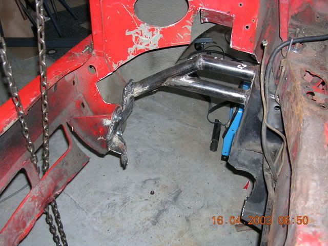
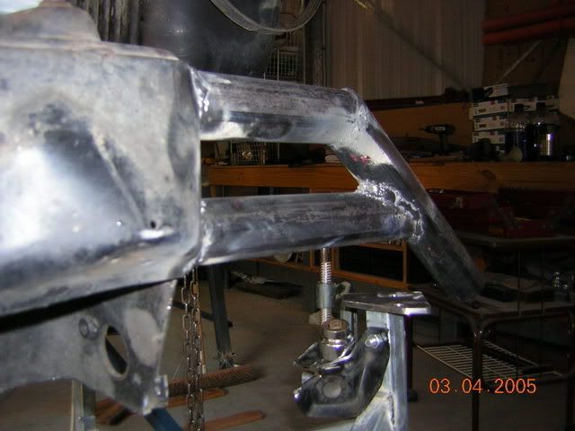
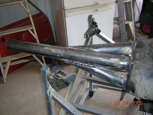
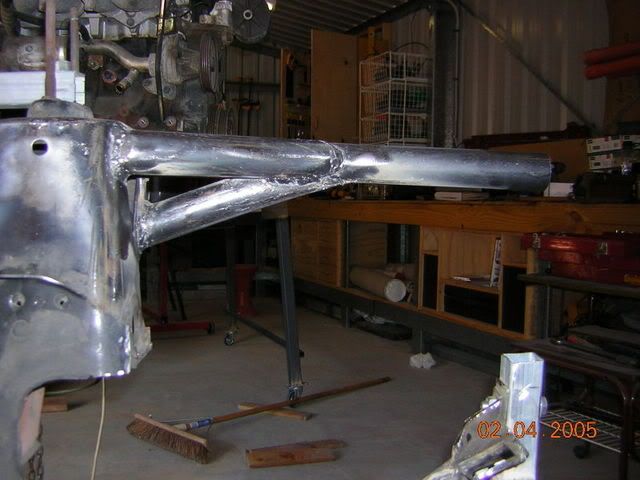
With both spars in place, its time to tie them into the front eyelets. On the drivers side, this involved cutting two 6mm steel plates of dissimilar shape to allow for the 'seam' of the bodywork where the front eyelet joins the body work. The spar was then obliquely slashed to join up with this plate. Also, it was at this time that the inner guard had to be cut to accomodate the new subframe.

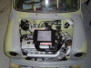
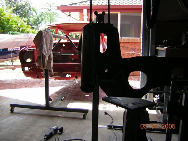
Pic of the subframe inside the bay during a test fit. the fit was very tight, but all holes lined up. Notice that I cut out more bodywork than I needed to (bugger!). This would be reinstated later on.
Image

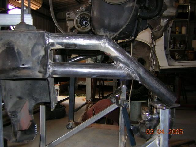
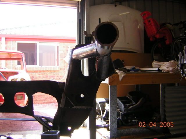
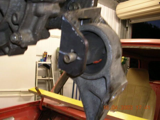
On the passenger side, the spar was redirected along the inner guard, and then turned down at 90 degress to emerge directly on top of the eyelet. The backside was cut out of the pipe by 6mm (thickness of the plate) to join onto the mounting plate that held the eylet and which mounted to the body:
Image

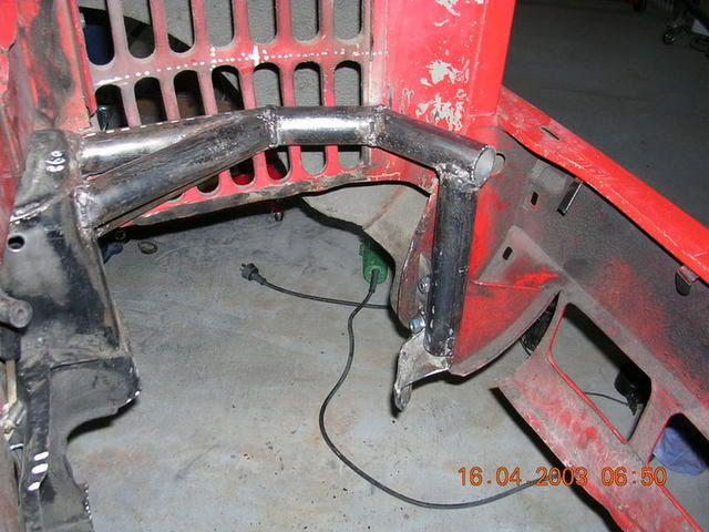
In the picture above, notice the space in front of the spar for the radiator. Also the space above the spar (where the original Mini radiator once lived) will now become the space for the cold-air box (it is mandatory in QLD that you cannot run an exposed air-cleaner or filter).

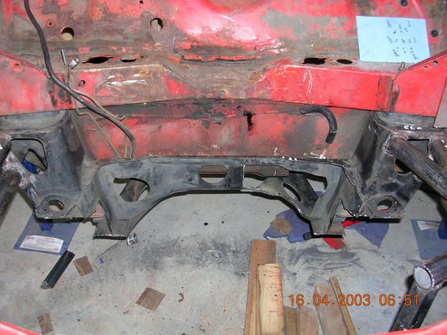
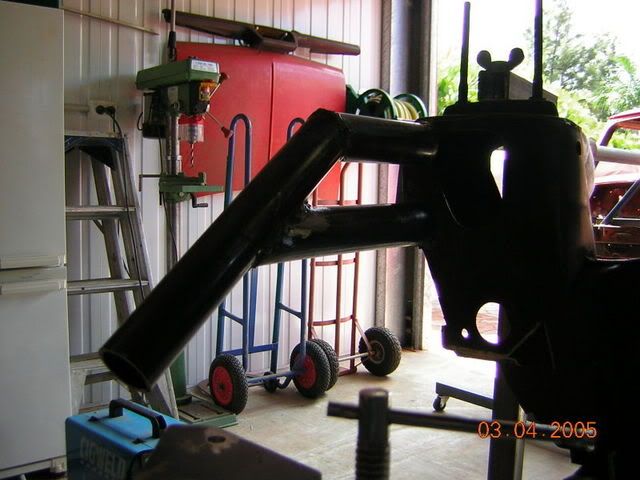
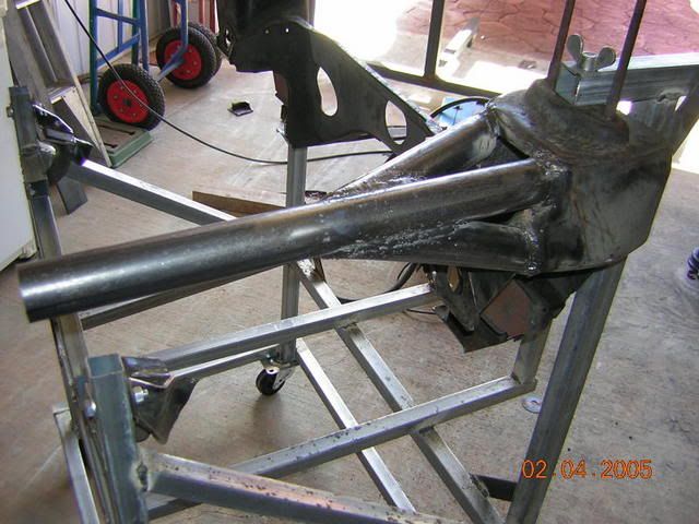
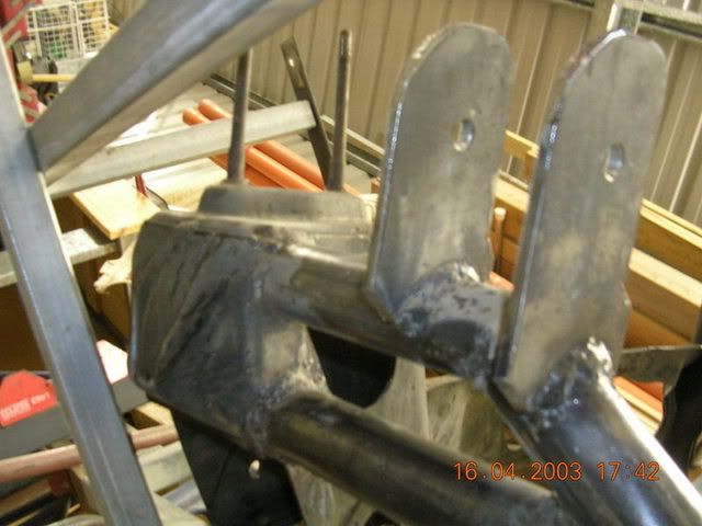
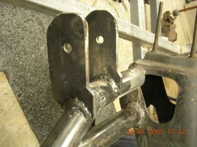
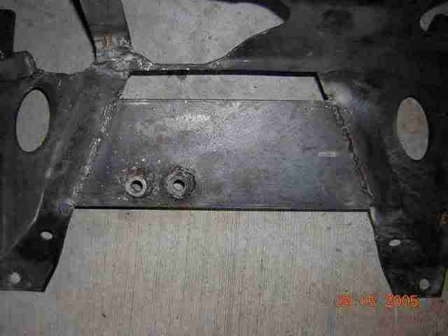
This is what the subframe looked like at the rear:
Image

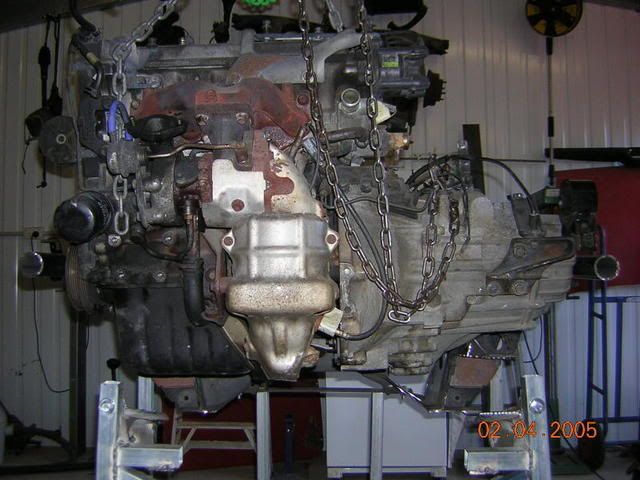
Now that the subframe was sitting in the engine bay nice and neat as you please, it was time to bring the engine in and fabricate the mounts. In the Starlet, the engine comes out from underneath. But I wanted the engine to come out from the top as well as come out from the bottom (this being one of the design criteria which influenced the overall design). To this end, the engine mounts had to cater for this design idea.

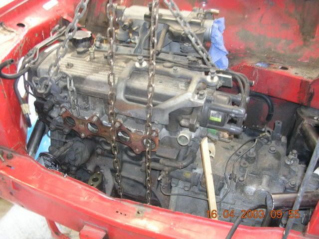
Once the engine and subframe was in the car, it was time to locate the engine precisely and take some measurements to allow the mounts to be fabricated.

Engine supported from underneath:
Image

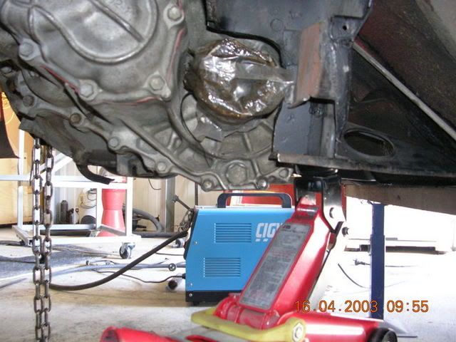
And pieces of wood used to gauge and enforce clearances:
Image

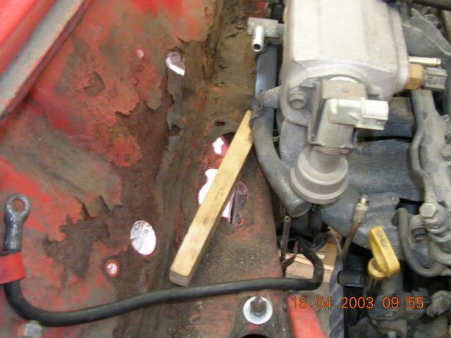
A bullet level was used on the plenum to ensure the motor was dead level. Also, after marking two identical marks on either front guard, a straight edge lined up with the exhaust manifold face was used to ensure the motor remained square:
Image

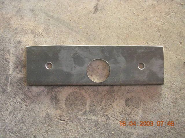
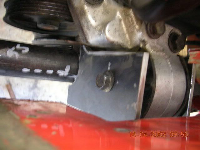
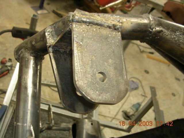
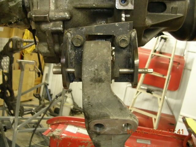
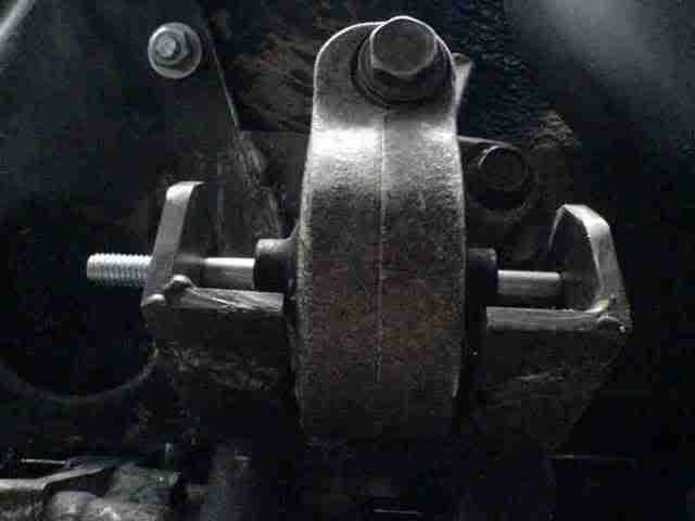
I started with the drivers side mount first. This was the easiest one. It was also the most crucial in that getting this one right would ensure that the motor was in position from left to right, and front to back. Firstly I took some measurements, and then fabricated the mount (the mount just being two upright leaves either side of the mount). I took the liberty of making either side out of one piece of steel, then cutting it across the middle. The hole (or actually half a hole when its disected) allows the mount to follow the contour of the round bar of the spar:
Image

Then the mount was bolted into place, and after checking it for accuracy, was tack welded on. I checked the clearences and alignment again - a perfect fit. Time to weld!
Image

Image

Image

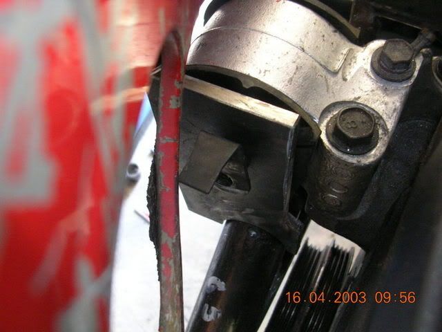
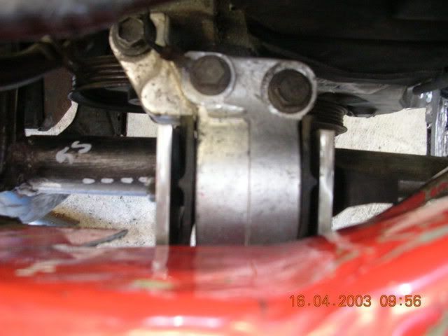
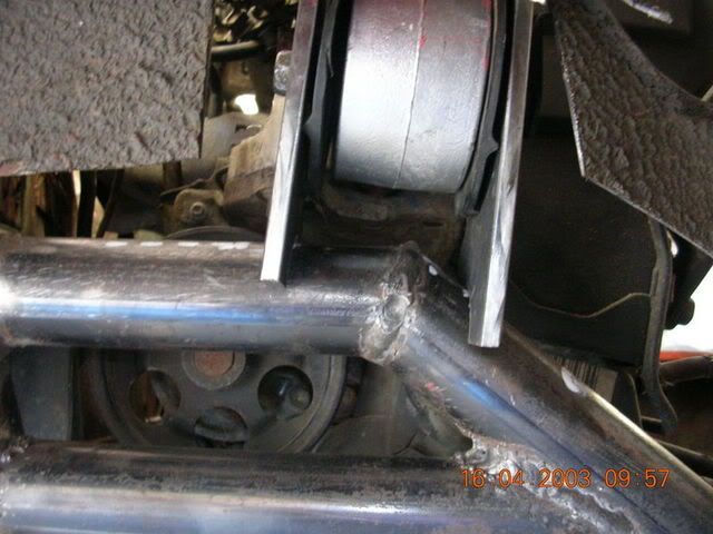
No - dont adjust your screen!! And no, your head isn't on a tilt. The motor had to be rotated about the driveshafts, forward, by about 3 degrees to facilitate clearance between the inlet plenum and the firewall. This shot of the drivers side mount reflects this necessity. The spar is actually dead level.
Image

_________________
"Not Speeding Officer..........Qualifying"


Top
 Profile  
 
 Post subject:
PostPosted: Thu Sep 21, 2006 10:06 pm 
Offline
1275cc
1275cc
User avatar

Joined: Fri Jun 17, 2005 10:31 am
Posts: 3183
Location: Burpengary, Queensland - Home of Tricky Performance Engineering
badassmini wrote:
Archangel007
were abouts in burpengary do you live i might have to pop round one day for a chat if thats ok


Badass,

PM sent.....

_________________
"Not Speeding Officer..........Qualifying"


Top
 Profile  
 
 Post subject:
PostPosted: Thu Sep 21, 2006 10:52 pm 
Offline
1275cc
1275cc
User avatar

Joined: Fri Jun 17, 2005 10:31 am
Posts: 3183
Location: Burpengary, Queensland - Home of Tricky Performance Engineering
Chapter 3 contd.

Here are pics of the finished drivers side mount - fully welded and profiled.
Image

Image

Now that the drivers side mount was done, it anchored the motor beautifully. The next mount to tackle was the passenger side. Another overriding factor in designing and fabricating the spars the way I have, is it allows me to use the original factory mounting brackets (motor-side) in the exact factory position. And we talked before of how crucial this was. To understand the gravity of this, ask yourself "Why did Toyota put that mount there, instead of here??'' There is a reason (one we may only guess at) but a very valid reason or reasons none the less.

The passenger side utilised the factory bracket as stated, in the factory position. Its shape was to be a simple box shape without sides, as the rubber mount part unbolted from the engine bracket part. However, on closer inspection, the leaves of the mount had to be offset some so the hole for the bolt went through the centre of each mount (the strongest part).

This is what ot looked like in the end:
Image

The motor at this stage could be sat in the subframe unaided. It was starting to look like something!! Now, onto the rear mount. The rear mount for me had to be able to anchor the engine, strengthen the subframe and not hinder the exhaust route. To this end I totally deviated from what anyone else had done - and came up with the simplest idea yet!!

A simple 100mm x 6mm plate was welded in between the two 'ears' of the rear of the front subframe. Onto this plate, blind nuts were welded in place to bolt up the rear mount.
Image

Next, the engine mount had to be modified. This is the original mount. It will be shortened after the first two bolt holes, and the engine mount side discarded and a new one fabricated:
Image

A simple open box mount was fabricated, which in turn bolted back into the factory position, but allowed the engine mount to slide slightly to the passenger side to allow clearance in the exhasut tunnel:
Image

Image

And once they were bolted together - perfect!! The rear mount was only 20mm left of the factory position, and provided an extremely secure anchoring point. Also, the flat plate across the 'ears' stiffened up the frame no end. There is zero torsional flex after this went in:
Image

Next chapter - we finish off the subframe, and move onto the ??? (Got you guessing??)

_________________
"Not Speeding Officer..........Qualifying"


Top
 Profile  
 
 Post subject:
PostPosted: Thu Sep 21, 2006 11:08 pm 
Offline
998cc
998cc
User avatar

Joined: Wed Jul 20, 2005 8:23 pm
Posts: 776
Location: Concord West, NSW
Subframe is looking good. In fact 10 out of 10 if you ask me.

If i was to do another subframe i would go down the same track what i see here.

Dan


Top
 Profile  
 
 Post subject:
PostPosted: Thu Sep 21, 2006 11:10 pm 
Offline
998cc
998cc
User avatar

Joined: Mon Jan 16, 2006 1:15 pm
Posts: 678
Location: Melbourne
Brilliant stuff Archangel,

I cant tell you how encouraging it is to see all of you guys doing this stuff. Now I just need to stop reading Ausmini and get out to the shed...

Madmorrie


Top
 Profile  
 
 Post subject:
PostPosted: Thu Sep 21, 2006 11:37 pm 
Offline
Yay For Hay!
User avatar

Joined: Wed Sep 08, 2004 9:27 pm
Posts: 15870
Location: Wodonga - Vic/NSW border
I have great admiration for your work on this Andy - it's teriffic

_________________
did I tell you that I won a trophy?


Top
 Profile  
 
 Post subject:
PostPosted: Fri Sep 22, 2006 8:11 am 
Offline
1275cc
1275cc
User avatar

Joined: Thu Jun 03, 2004 2:56 pm
Posts: 3981
Location: Brisbane
AT,

You might show subtle modifications required when completing both Tony's and my car? This will further show how well this style of frame is designed and built (note - has been used on a morris).

Actually - Peeps there are some pics of the frame we build for my car in my photbucket album (link in sig).

JC

_________________
But he's thriving and striving and hugging the turns.


Top
 Profile  
 
Display posts from previous:  Sort by  
Post new topic Reply to topic  [ 1864 posts ]  Go to page Previous  1, 2, 3, 4, 5 ... 125  Next

All times are UTC + 10 hours


Who is online

Users browsing this forum: No registered users and 116 guests


You cannot post new topics in this forum
You cannot reply to topics in this forum
You cannot edit your posts in this forum
You cannot delete your posts in this forum
You cannot post attachments in this forum

Jump to:  

© 2016 Ausmini. All garage work involves equal measures of enthusiasm, ingenuity and a fair degree of irresponsibility.