Ausmini
It is currently Wed Apr 24, 2024 12:30 pm

All times are UTC + 10 hours


Post new topic Reply to topic  [ 1864 posts ]  Go to page Previous  1, 2, 3, 4, 5, 6 ... 125  Next
Author Message
 Post subject:
PostPosted: Sat Sep 23, 2006 2:38 pm 
Offline
1275cc
1275cc
User avatar

Joined: Fri Jun 17, 2005 10:31 am
Posts: 3183
Location: Burpengary, Queensland - Home of Tricky Performance Engineering
Chapter 4 - Finishing the Subframe.

Okay, where were we? Ah, yes, the subframe. Last chapter we saw the makings of a beautiful friendship between the new subframe, new motor and old body (sounds a bit like me!!). We could in fact, stop here and the motor would be in situ, but in fact, there are some minor amendments we will have to make to the subframe to deem the motor operational.

First up - rigidity. Along the lines of Matt's design, a transverse bar was to go in between the towers. The purpose of this bar was simply to transfer lateral loads from one side to the other, so that the two towers (and their respective anchoring points) now shared the loads instead of one. Sounds simple, in fact it is.

To do this we simply need to weld in a bar from one tower to the other. In my view the best position is as high as it can go, so the transfer point is as close to the mounting point as possible. The problem I had to sort out though is, if I intended to use the 38mm pipe (and I did) then the bar had to go back as far against the firewall as possible to allow the diff to pass clear when extracting the engine from the top.

The diff on the VLSD model sticks out to the rear of the engine further than a standard open diff, with a mounting lug cast into the diff housing. Since this lug served no purpose in the new installation (it mounted to nothing and nothing mounted to it - simply a lifting lug as far as I could tell) then off it came with the grinder.

The shiny patch on the casing is where the lug used to be:
Image

The fact that this lug was now removed, made no difference to the location of the transverse bar however (sadly). So, it was cut and welded into place:
Image

Now, with the bar as far back against the firewall as possible, how was I to get the brake line and battery cable (et al) to the rear of the car, as the bar effectively closes off this route?? Simple, pockets. I cut two pockets into the rear bar, and then boxed then out with 3mm plate. This then formed a 1omm deep channel for the services to go down the firewall in their original positions, unheeded.

This is what the pockets looked like:
Image

Now the next challenge, that Matt also faced was the fact that with the motor in the position that it is, the gear change lever fouls on the passenger side tower, and can not go full travel. So, the answer, you guessed it, another pocket. This time the pocket consisted off a small piece of 38mm pipe, cut longitudinally down the centre, and then this welded into the square that was cut out of the tower.

The fouling lever:
Image

And the pocket that alleviated the interference:
Image

Alright, two problems (which we knew about) solved. The subframe could now be deemed to be fully operational and functional.

But it doesnt end there, we arent quite finished yet. El Gato was always meant to have the performance to match its looks and handling. Even before a panel was cut, I knew that a front mount inter-cooler (FMIC) was to go on, to replace the very inefficient top-mount (TMIC). the TMIC suffers from engine bay heat-soak,and lack of forced slipstream across its surface to aid in the heat transfer process. A FMIC is much more efficient with its bar and plate design and increased surface arrea that is fully exposed to the frontal slipstream.

This FMIC has to mount to somewhere, ideally the subframe as it is a rigid structural member. To do this a link bar had to be fabricated to bridge betwen the two tie-rod anchoring eyelets. The reason fo this link is:
1. It stabilises the two eyelets and stops them spreading or coming together
2. It reinforces the body work, and will stop any inherent vibration once the inner guards have been cut
3. It mounts the FMIC firmly.

Now, one could link the two sides of the subframe with just a straight parallel bar. But, in the interests of forward planning I chose not to. The reason for this was:
1. I needed as much room at the front of the engine as possible because I always intended to replace the CT9 with a larger turbo
2. It would be well away from the exhaust dump pipe and have no chance of ever coming into contact with it if one, or even two, engine mounts broke.
3. In the interests of a larger turbo, a custom tuned length manifold was envisaged so the bar had to be out of the way of other stuff as well, like the radiator etc.

To make this bar work, some of the front apron of the body had to be rearranged to suit where the bar was to go. Basically, I cut two slits up the sides of the front panel, right next to the box that mounts the body to the subframe, and pushed it forward a couple of inches. Then, I just profiled two fill in pieces and welded them in place. The result was a good looking front section that was as strong as the original.

Pushing the front panel forward a couple of inches also had a side benefit, it stopped the air cavitating at the rear of the FMIC. (Basically, air that has gone through the FMIC meets up with air that has gone underneath, and this creates a higher pressure state of confused air which then restricts the air coming through the FMIC).

This is what the front panel looks like now in profile:
Image

And from behind. The actual shape of it looks better than the factory option in my humble opinion:
Image

As you can see in the above picture, the front link bar has a set in it to make it protrude as far forward as possible. The set angle was about 35 degrees. The ends of the bars were slash cut so as to mount onto the front side of the eyelet mounting plates. Now that this was fabricated and welded in, two tabs were welded on and then drilled and tapped for 6mm bolts, so as to mount the FMIC lower bracket.

Now, the only thing left to do was to fully seam-weld the rest fo the subframe. The tops of the towers, the rear 'ears' and anywhere else that was spot-welded, was fully seam welded. The end result, was a subframe with zero torsional flex, zero lateral and longitudinal flex, and only about 8 kg's heavier (this doesnt matter, as the 4EFTE is about 20+kg's lighter than the A-series - so a net loss of weight in the end).

This is the finished product:
Image

Image

Image

Now that the subframe was fully completed, it is time to turn our attention to the engine bay, which we have already master-planned. Join me next time as we say - "Thank f#ck I thought of that!" and "Isn't it getting crowded in there!". We also get to meet a real character that ended up becoming a close personal friend (hint: he is 63 and has stripes!)

_________________
"Not Speeding Officer..........Qualifying"


Top
 Profile  
 
 Post subject:
PostPosted: Sat Sep 23, 2006 2:41 pm 
Offline
1275cc
1275cc
User avatar

Joined: Fri Jun 17, 2005 10:31 am
Posts: 3183
Location: Burpengary, Queensland - Home of Tricky Performance Engineering
striped 63 wrote:
AT,

You might show subtle modifications required when completing both Tony's and my car? This will further show how well this style of frame is designed and built (note - has been used on a morris).

Actually - Peeps there are some pics of the frame we build for my car in my photbucket album (link in sig).

JC


Hi JC - brilliant suggestion. Before I satrt the next chapter, if the readers Ok it I might just digress and show them how the subframe has 'evolved' since the first one. If they are going to copy this design, its better they copy the latest one.

Cheers,
Tricky

_________________
"Not Speeding Officer..........Qualifying"


Top
 Profile  
 
 Post subject:
PostPosted: Sat Sep 23, 2006 3:24 pm 
Offline
998cc
998cc
User avatar

Joined: Sun Jun 11, 2006 2:15 pm
Posts: 604
Location: caboolture qld
yeah show us the new design to the fram looks great.
cheers

_________________
Cheers Dan

FIRST COMES THE MONEY, THEN COMES THE POWER, THEN COMES THE WOMEN.!!


Top
 Profile  
 
 Post subject:
PostPosted: Sat Sep 23, 2006 6:01 pm 
Offline
1098cc
1098cc
User avatar

Joined: Sun Oct 10, 2004 4:04 pm
Posts: 1533
Location: melbourne, victoria
inspiring work there. You make it sound so simple and easy

Would you make more if people wanted them?

DAVID


Top
 Profile  
 
 Post subject:
PostPosted: Sun Sep 24, 2006 6:32 am 
Offline
1275cc
1275cc
User avatar

Joined: Fri Jun 17, 2005 10:31 am
Posts: 3183
Location: Burpengary, Queensland - Home of Tricky Performance Engineering
floss wrote:
inspiring work there. You make it sound so simple and easy

Would you make more if people wanted them?

DAVID


Hi David,

We have made quite a few now so we believe we have got it down to a fine art.

If you wanted a subframe built, we can accomodate you.

Turnaround would be under a week. :lol:

Cheers,
Tricky

_________________
"Not Speeding Officer..........Qualifying"


Top
 Profile  
 
 Post subject:
PostPosted: Sun Sep 24, 2006 6:35 am 
Offline
1275cc
1275cc
User avatar

Joined: Fri Jun 17, 2005 10:31 am
Posts: 3183
Location: Burpengary, Queensland - Home of Tricky Performance Engineering
minimetoy wrote:
Subframe is looking good. In fact 10 out of 10 if you ask me.

If i was to do another subframe i would go down the same track what i see here.

Dan


Hi praise indeed Dan.

Thank you.

Cheers,
Tricky

_________________
"Not Speeding Officer..........Qualifying"


Top
 Profile  
 
 Post subject:
PostPosted: Sun Sep 24, 2006 6:37 am 
Offline
1275cc
1275cc
User avatar

Joined: Fri Jun 17, 2005 10:31 am
Posts: 3183
Location: Burpengary, Queensland - Home of Tricky Performance Engineering
skssgn wrote:
I have great admiration for your work on this Andy - it's teriffic


Ahh Simon, you make me feel all warm and fuxzzy inside!!

Your just buttering me up for when our "collaborative" project starts!

You old smoothie you!!

_________________
"Not Speeding Officer..........Qualifying"


Top
 Profile  
 
 Post subject:
PostPosted: Sun Sep 24, 2006 8:51 am 
Offline
1098cc
1098cc
User avatar

Joined: Sun Oct 10, 2004 4:04 pm
Posts: 1533
Location: melbourne, victoria
that is cool...

I wont be buying one for a while but have dreamt about it for ages. Still paying off my last mini purchase. almost all done. I am saving to buy a house also.

Would your frame suit clubbie/roundie and a moke?
Like the way the fmic and the cut outs look. Would like to see it painted, i think it would look stellar (the cut out)


Top
 Profile  
 
 Post subject:
PostPosted: Sun Sep 24, 2006 9:07 am 
Offline
1275cc
1275cc
User avatar

Joined: Fri Jun 17, 2005 10:31 am
Posts: 3183
Location: Burpengary, Queensland - Home of Tricky Performance Engineering
Chapter 5 - An Evolutionary Design

So, the subframe was complete, the music played and the beer flowed. There were smiles in the camp at Qik Brix Racing. It was about the time that the subframe was finished that the QLD Mini Muster came around. So, in the interests of professional curiosity, my mate Tony and I decided to go along.

While at the show, I had the fortune to meet a really nice guy called John Carter, or JC to his mates. He had a 1963 Morris that he was putting a Swift Gti motor into, so when I told him about the Starlet, we kind of bonded right away. Most of you know JC on the forum as Whitestripe 63. It was JC who actually introduced me to this forum in fact.

Anyway, JC and I would form a strong friendship over the next year and a half, and in my book, he is a really top bloke. The first I saw JC's mini (Hefty) was when I offered to help him move it from his old digs to his new place. It was a really nice deseamed 63 Morris in Midnight blue with twin white racing stripes down the centre of the car (hence the name!). Anyway the car was delivered successfully but JC then informed me that he had sold all his GTi stuff and was intending to do a 4EFTE instead. Since he had no workshop of his own, I offered my place, and Hefty's new heart transplant was started in earnest.

Now, doing a 4EFTE in a Morris poses some serious design challenges. Its obvious that the engine bay is some 50mm shorter than the Clubman, and not as wide due to the way the inner guards angle in, and also it has a swooping bonnet line. So, some design criteria had to be adhered to to make the transplant successful. These were:
1. The motor had to sit far enough back as to get a front mount radiator in the engine bay
2. Minimal cutting of inner guards
3. No changing of the bonnet or bonnet line
4. Enough space at the front to allow the turbo to sit behind the grill.
5. The original Toyota factory mounts had to be in the std factory position (or as close to it as humanly possible)
6. Impact zones and crush zones still had to be engineered into the design
7. The engine had to be able to be removed from the top

Tough!!! So the std Qik Brix Racing (QBR) subframe had to be redesigned to accomodate the above. The drivers side spars would work with only slight modification - but the passenger side would need major rework. Lets look at the drivers side first.

Because the engine bay is shorter than the clubman, back-to-back, it became immeditely apparent that the drivers side spar would never meet the eyelets at the current angle of declination of the spar. Two possible courses of action.
1. Increase the existing angle until it meets the eyelet at the front at the same level, or:
2. Put another set into the pipe to get it to drop almost vertically onto the eyelet plate.

The second option was chosen because of two reasons:
1. The existing spar design on that side was rock-solid and worked.
2. Increasing the angle decreased the length of the underside supporting spar, therefore decreasing its supportive load carrying ability (not good)
3. The engine mount 'ears' on that side would have been grossly uneven, and would have been much harder to manufacture
4. The engineer had already signed off on my frame so why mess with a good thing!

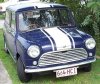
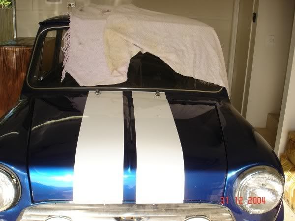
Here's pic of Hefty before the operation:
Image

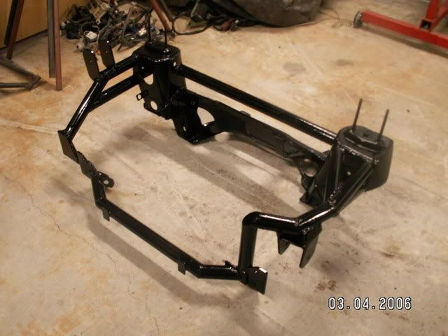
The subframe stared out exactly as before - single spar on the passenger side with lateral and longitudinal support spars, and drivers side single spar with longitudinal support spar:
Image

Image

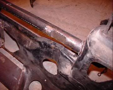
So, on the drivers side we swooped the spar down well after the engine mount position so that it met the eyelet plate. Then the spar was slach cut and welded into place. It was extremely important to keep the spar perfectly plumb throughout the process.
Image

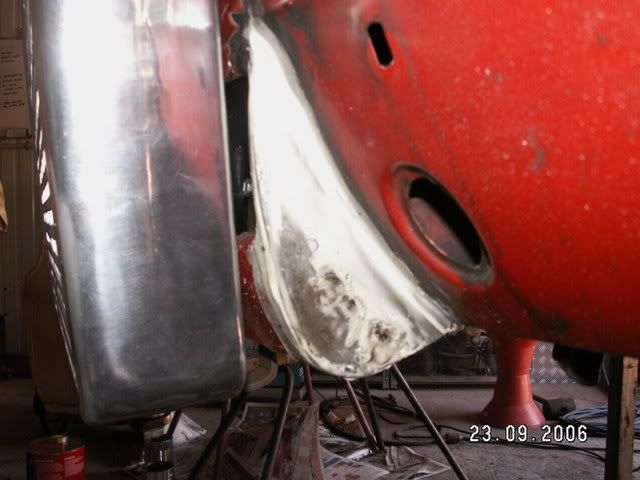
Right, passenger side. This posed some problems, but we decided that the easiest way of dealing with them was to keep the spar out of the engine bay altogether. In fact, the passenger side spar reflected somewhat that of the drivers side. The only difference was that the angles changed because we needed a flat (horizontal) area to locate the engine mount. The spar was slash cut at the end to make it fit onto the eyelet plate as per the drivers side. This is how it turned out:

Image

OK, spars done and looking good. Onto the engine mounts. The drivers sdie posed no problems. Two upright ears straddling the factory mount, located in the existing factory position. This side always seems to be dead easy - and it is. The standard mount for this side could now be utilised. However, instead of making it out of 6mm 250 grade steel I decided instead to make it out of 340 grade 5mm plate. Much nicer and just as strong (especially in shear).

Image

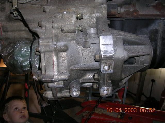
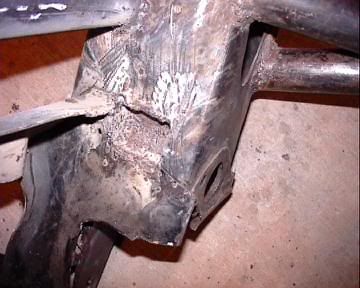
Now the passenger side. There was no way, come hell or high water (very biblical that!) that the passenger side mount was going to either utilise the factory cast mount, or be located in the factory position - no way, just not enough room. So instead, the mount was located higher than the original, and further rearward. To do this, a custom engine mount plate had to be made. This was done by profiling a length of 75 x 5mm 340 grade plate with a series of grinder cuts to the profile of the gearbox casing. This is what I mean:
Image

Once the plate was drilled and bolted down tight onto the gearbox casing, it was tack welded, removed and then fully welded up. This is it back on the gearbox for a test fit. It utlised all six 12mm mounting points (rock solid anchoring!!)
Image

The upstand part of the mount was then fabricated to allow the mount to be positioned in such a way that a box section subframe mount could be used. This mount took me one whole day to do - a lot of that was just in the design!! Once the pivot pin is removed, the mount can now be unbolted from the engine plate, and then the engine plate unbolted from the gearbox casing. Once this is done, it is easy to get the engine out from the top. here are three pics of the passenger side engine mount - I can honestly tell you I am very proud of how this came out.
Image

Image

Image

Okay, onto the rear engine mount. The tried and true procedure that i used on my subframe for El Gato was used for Hefty - it was dead simple to make, and it worked!!! Why mess with it. Firstly, a spreader plate was cut and welded in between the 'ears' of the subframe and two blind nuts welded on:
Image

Then the rear mount engine bracket was made. Simply, it was the same as what I had used on El Gato except the shape of it was modernised to follow the curves of the factory rubber mount:
Image

The factory mount was then shortened. Once the engine-side mount was bolted up, and the subframe-side was bolted on, it was simply a simple matter of running in the pivot pin (engine mount bolt). This was high-tensile of course! Here are the pics of the finished product.
Image

Image

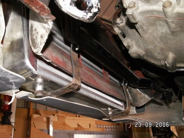
The end result was that we had heaps of room for the exhaust, and pleanty of under-car clearance.

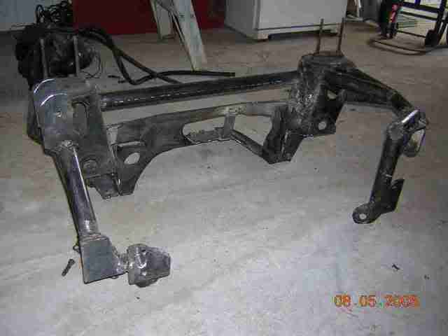
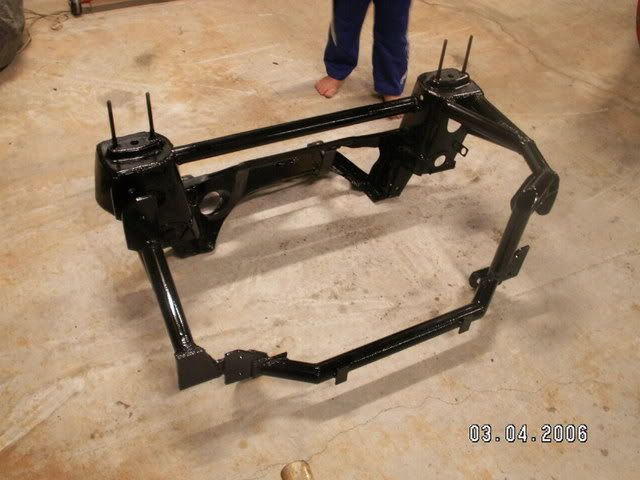
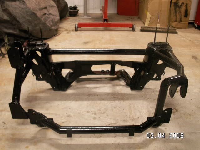
Here is a pic of the finished subframe (with a smiling JC!). The cross-bar is in between the towers, and the subframe has been fully seam-welded up. Also, the tabs for the brake lines have been welded on (something I forgot to mention in Chapter 6).
Image

Notice the front eyelet mounting plates. The return that you see jutting out to the front is for the link-bar between the eyelets. For the Morris, this link bar will be rmovable and secured by tapped 8mm bolts into the eyelet plate.

With the Clubman, the subframe is identical except the main spar angles where they bend down have been reduced slightly to cater for the longer back-to-front engine bay distance. Also, the passenger side engine mount is a straight forward drop-down mount consisting of two leaves either side of the rubber engine mount.

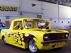
Here is the 4EFTE mounted in 'Barbie':
Image

This is Barbie's drivers side mount. Nice and simple but strong.
Image

And this is the passenger side mount. It gives good clearance, and keeps the mount in the factory position. Tony now has heaps of room at the front for radiator and FMIC!!
Image

This is the design that QBR will stick with for any future Starlet conversions - simple, strong, and aesthetically pleasing.

A big thanks to JC for supplying all the photos of Hefty's conversion (thanks mate!).

_________________
"Not Speeding Officer..........Qualifying"


Top
 Profile  
 
 Post subject:
PostPosted: Sun Sep 24, 2006 9:45 am 
Offline
THIS SPACE FOR RENT
User avatar

Joined: Wed Jun 09, 2004 3:35 pm
Posts: 11848
simply put..i am in awe...

brilliant work.....

_________________
Image


Top
 Profile  
 
 Post subject:
PostPosted: Sun Sep 24, 2006 2:36 pm 
Offline
1275cc
1275cc
User avatar

Joined: Thu Jun 03, 2004 2:56 pm
Posts: 3981
Location: Brisbane
Wait until we get back onto El Gato Cush. It just gets better.

Note - When AT said a week. We rolled mine in on Saturday morning. Rolled out with Starlet motor mounted on Tuesday morning.

_________________
But he's thriving and striving and hugging the turns.


Last edited by JC on Sun Sep 24, 2006 2:42 pm, edited 1 time in total.

Top
 Profile  
 
 Post subject:
PostPosted: Sun Sep 24, 2006 2:39 pm 
Offline
THIS SPACE FOR RENT
User avatar

Joined: Wed Jun 09, 2004 3:35 pm
Posts: 11848
tissues on standby.... :)

_________________
Image


Top
 Profile  
 
 Post subject:
PostPosted: Sun Sep 24, 2006 4:15 pm 
Offline
998cc
998cc
User avatar

Joined: Sun Jun 11, 2006 2:15 pm
Posts: 604
Location: caboolture qld
Archangel007 your one smart man

_________________
Cheers Dan

FIRST COMES THE MONEY, THEN COMES THE POWER, THEN COMES THE WOMEN.!!


Top
 Profile  
 
 Post subject:
PostPosted: Sun Sep 24, 2006 5:49 pm 
Offline
1098cc
1098cc
User avatar

Joined: Sun Oct 10, 2004 4:04 pm
Posts: 1533
Location: melbourne, victoria
so where do we drop our minis off to get them done ? :) :)
do we put a figure on the cheque or just sign it :) :)


Top
 Profile  
 
 Post subject:
PostPosted: Sun Sep 24, 2006 5:59 pm 
Offline
1098cc
1098cc
User avatar

Joined: Fri Nov 26, 2004 7:07 pm
Posts: 1647
Location: New York City
Archangel007 wrote:
Anyway, JC and I would form a strong friendship over the next year and a half, and in my book, he is a really top bloke.


Seconded.... top bloke that is....

now if only the bugger would stop trying to convince me to do a conversion. :wink:

_________________
"Life is not like a box of chocolates... it's more like a jar of jalapenos. Whatever you do today, may burn your arse tomorrow."


Top
 Profile  
 
Display posts from previous:  Sort by  
Post new topic Reply to topic  [ 1864 posts ]  Go to page Previous  1, 2, 3, 4, 5, 6 ... 125  Next

All times are UTC + 10 hours


Who is online

Users browsing this forum: No registered users and 21 guests


You cannot post new topics in this forum
You cannot reply to topics in this forum
You cannot edit your posts in this forum
You cannot delete your posts in this forum
You cannot post attachments in this forum

Jump to:  

© 2016 Ausmini. All garage work involves equal measures of enthusiasm, ingenuity and a fair degree of irresponsibility.