Ausmini
It is currently Fri Apr 26, 2024 1:27 am

All times are UTC + 10 hours


Post new topic Reply to topic  [ 1864 posts ]  Go to page Previous  1, 2, 3, 4, 5, 6, 7 ... 125  Next
Author Message
 Post subject:
PostPosted: Sun Sep 24, 2006 9:31 pm 
Offline
848cc
848cc
User avatar

Joined: Mon Sep 11, 2006 6:36 pm
Posts: 26
Location: Kallangur,Brisbane
Quote:
floss wrote:
inspiring work there. You make it sound so simple and easy

Would you make more if people wanted them?

DAVID


Hi David,

We have made quite a few now so we believe we have got it down to a fine art.

If you wanted a subframe built, we can accomodate you.

Turnaround would be under a week.

Cheers,
Tricky


This sounds very tempting, another thing I can "outsource". How would the subframe handle hanging a liftoff front (new it would come in handy), then i asume you don't have worry about it inner guards. :D
Have your subframes been blueplated in Qld yet?


Top
 Profile  
 
 Post subject:
PostPosted: Mon Sep 25, 2006 7:03 pm 
Offline
1275cc
1275cc
User avatar

Joined: Fri Jun 17, 2005 10:31 am
Posts: 3183
Location: Burpengary, Queensland - Home of Tricky Performance Engineering
Hoon,

No worries about compliance, the engineer has been along for the entire ride (I'll get to that in chapter 6!)

Subframe would handle lift-off or tilt front end no worries. Actually, would work a treat!

Let me know the details and I can design something.

Cheers,
Tricky

_________________
"Not Speeding Officer..........Qualifying"


Top
 Profile  
 
 Post subject:
PostPosted: Wed Sep 27, 2006 8:37 am 
Offline
848cc
848cc
User avatar

Joined: Tue Apr 12, 2005 3:58 am
Posts: 426
Location: On a mission...
Archangel007 wrote:
I wanted a car that was different, and more dramatic than subtle.


"Dramatic" is an interesting term! There is no doubt it will demand attention.

It's decieving at how nicely positioned this is in the engine bay unless you see it in the flesh. I really do like this later evolution of the subframe and how low it places the engine.
http://i18.photobucket.com/albums/b117/ ... tos045.jpg

Looking forward to the next installment Tricky. No photographs of my welding either please :oops:

_________________
Metal to burn, sparks to fly...


Top
 Profile  
 
 Post subject:
PostPosted: Thu Sep 28, 2006 9:31 pm 
Offline
1275cc
1275cc
User avatar

Joined: Fri Jun 17, 2005 10:31 am
Posts: 3183
Location: Burpengary, Queensland - Home of Tricky Performance Engineering
Chapter 6 - The Engine Bay

Evening Viewers!

This chapter actually precedes chapters 4 and 5, because all the planning was done before the subframe was actually built. However, if the viewers would allow me some poetic license, then I will put it here. Basically the whole car has been masterplanned, with a place for everything and everything in its place so to speak. But before we get into it, lets start with a couple of truths that I like to adhere to and to answer a question from the viewers.

Truths:
1. Its better to spend 2 hours planning and 1 hour doing than to rush in and then spend 3 hours undoing!!
2. If its worth doing, its worth doing right (the first time!)

Now, one of the viewers asked whether the subrames have been blue plated, and the answer is no. Because, simply, they arent at that stage to be done yet. El Gato isnt on the road yet, and wont be for a couple of months. But in saying all this, let me reassure people who potentially want to copy the QBR subframe, or want QBR to do one for them. We have had the engineer, a gentle, thoughtful and very thorough guy called Gary Bow, along for the journey since day one. Even before we put grinder to steel, a 70-page methodolgy report was submitted for his review and comment. So impressed was Gary, and QBR's attitude to a) getting it right, and b) to having the Engineer involved from the start, that he gave us a long line.

When it came time to inspect the subframe in the car (1st Inspection), the dialogue went something like this (verbatim).

Gary and I were resting on the fenders of the car, looking at the subframe in the engine bay:
Tricky: 'So, what do you think?'
Gary: Very good indeed, shows a lot of thought'
Tricky: 'Umm, do you think its strong enough, do you think it needs any more reinforcing?'
Gary turns to me with an odd expression on his face: 'Do YOU think it needs any more reinforcing?'
Tricky thinking this was a trick question: 'Err, no not really!'
Garry nodding his head: 'Damn straight. Thing could hold up a bloody V8!'
Tricky: (smiles)
Gary gets up from the engine bay and stretches his back: 'Well, see you in a couple of weeks when the engine is in and the engine bay is complete. And remember what I said about braided lines!'
Tricky: 'Sure Gary, I'll give you a call when I am ready''

And that was the first inspection in a nutshell. We'll get tot the second inspection later.
So, masterplanning - what is it and how do you do it. Well simply really. Its just a case of planning where everything will go, before you start to build. With me, I made mock-ups of timber, cardboard or the real thing. How did I know what I would need, fairly simple again, I asked the Engineer. By writing a methodolgy statement and asking him to review it, I had a much greater understanding of what needed to go in, and what didnt. The braided lines where a good example. The Engineer said - 'Do not put braided brake lines in the engine bay. Solid only. I wont pass it if you do!' So, lets plan.

The first thing ever to be designed by me for the Mini was the radiator. It was the most important subsytem, and took up the most dedicated space - right in front! I took some measurements of the available space, and made a mock up of the radiator out of timber to see if it would work. It did! So, from there I sat down and designed the radiator using common core widths and heights. This is what I came up with:
Image
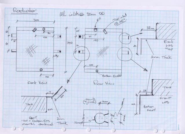
Paul Denooyer from P&F Fabrications was sent the drawing, and this is what came back!
Image
Image
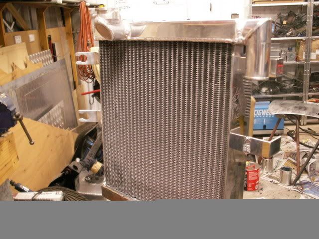
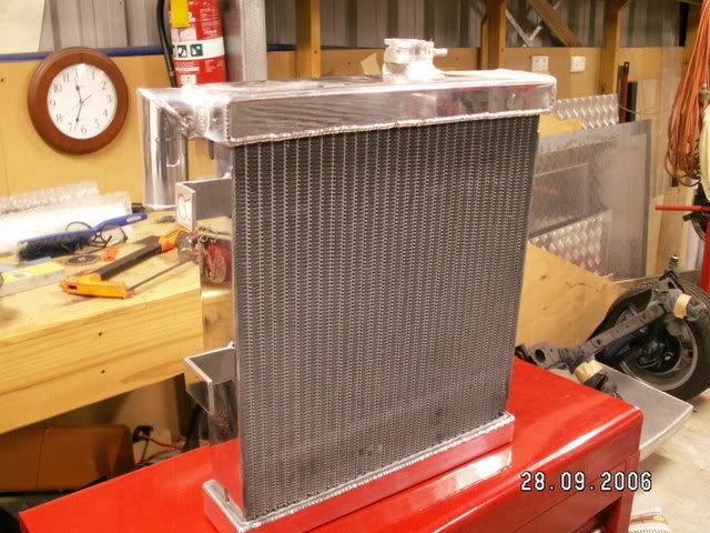
Bloody lovely and the guys from PWR said no worries with cooling at all!

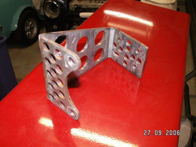
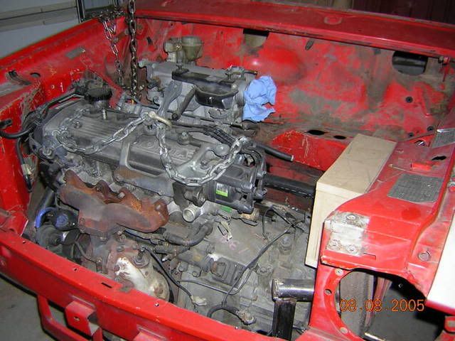
I was informed by the Engineer that my assumption to have boosted brakes was a correct. And uprated boosted brakes at that. So, where to put the booster. the simplest place was over the gearbox, that was where the most space was. To do this I had to make a custom bracket to mount it. It ended up looking like this:
Image
And this is how the booster mounts to the bracket:
Image
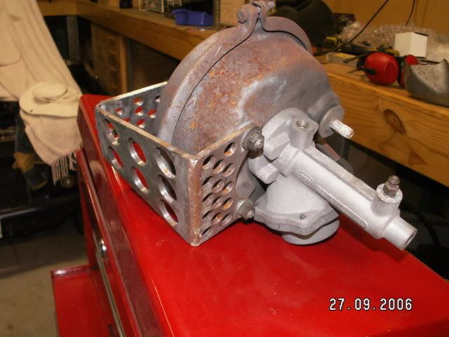
And this is where it mounts to. It sits slightly over the gearbox:
Image

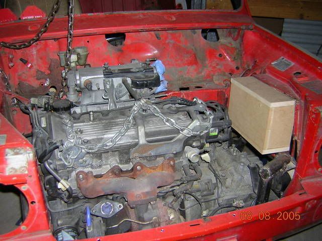
Next came the cold air box. I knew where it would go even before I put the engine in. It had to get cold air from outside the engine bay, but actually sit inside the engine bay itself. There was only one place, where the old Mini radiator once lived. I made a mock-up of the box out of MDF, and then checked it for fit etc. Believe it or not it holds over 6 litres. It will act as a plug for when I make it out of carbon fibre, with a removable lid. A K&N filter will sit inside, and it will be ram-air fed from the front of the car, through a duct in the front spoiler. Why have I gone to such lengths when a pod filter would be so much easier. The following:
1. Exposed pod filters are illegal in QLD
2. By using a cold air box, it intakes cold air, not warm engine bay air
3. By using an enclosed and sealed airbox, one can force feed it from the slipstream and gain a precious few hp for free.
4. Someone pinched the standard Starlet one from the halfcut before I collected it
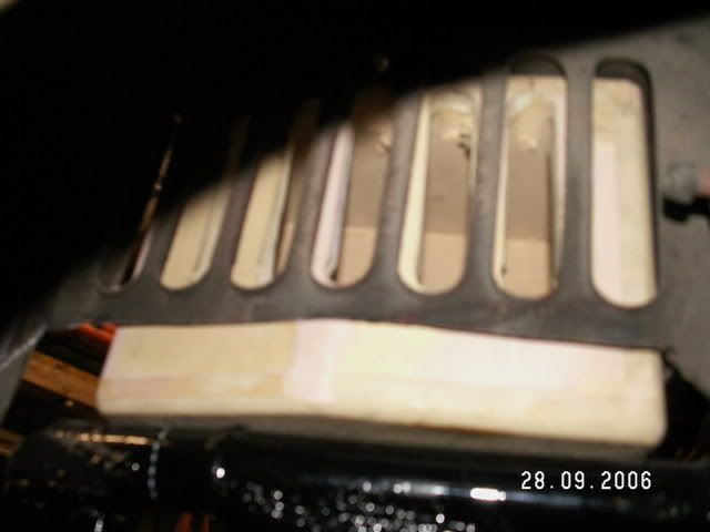
The airbox mould (plug actually). The circle shows where the exit path for the compressor intake will be:
Image
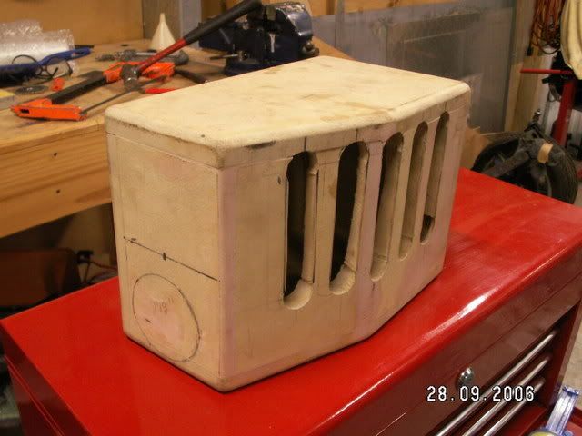
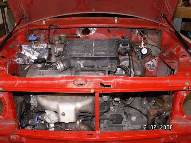
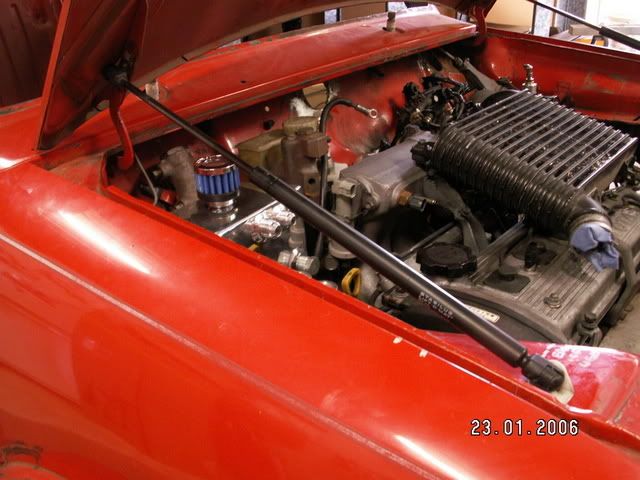
Inside the engine bay. Imagine it made of carbon fibre! (strong and light!) Image
Image
And on the outside. A cover will go on this side about 30mm wide, with a 21/2 inch snout leading to the front. It will also made of carbon fibre. It will be held in place by screws going right through the lid and inside guard. Sealing will be by foam strip. Should gain 3 or 4 hp on the track (ala road bikes etc)
Image

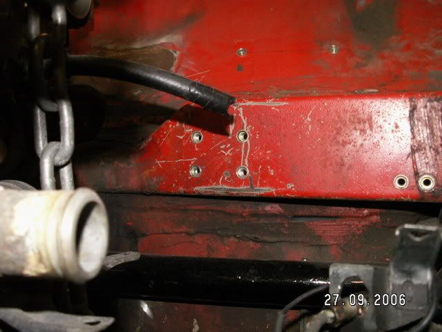
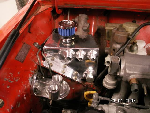
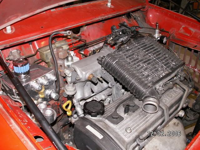
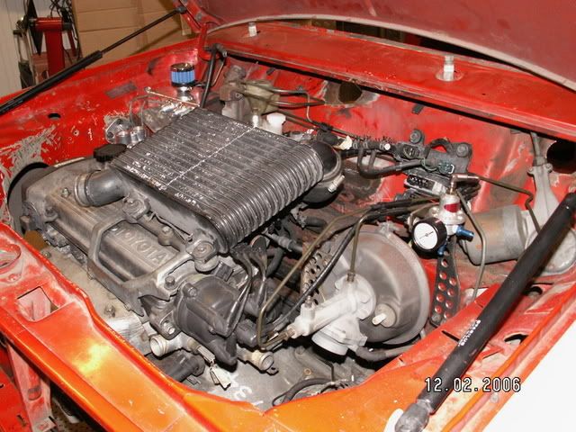
Once those two were taken care of, the fuel pressure regulator (FPR) had to live somewhere. I had decided early on that an aftermarket FPR would be used, to allow spot-on fuel pressures which would aid tuning. I purchased a Sard, rising rate FPR for about $200 from a performance wharehouse. This is where it sits (mainly because it has a gauge, and I wanted the gauge plainly visible), on its own little bracket (drilled for lightenss of course) right above where the fuel lines go down the firewall. This also shows the booster mounted to the firewall:
Image

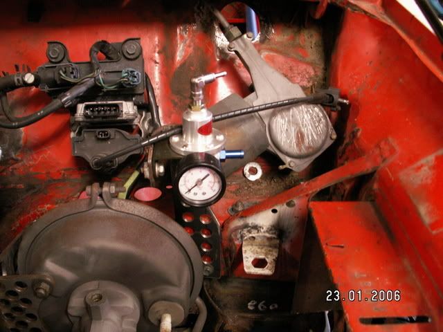
From the above picture you can see where the coil pack and solenoids will be mounted. Fairly straightforward position! You may also note that the bracket for the clutch line has been cut off the Starlet half-cut and welded into the Mini engine bay.

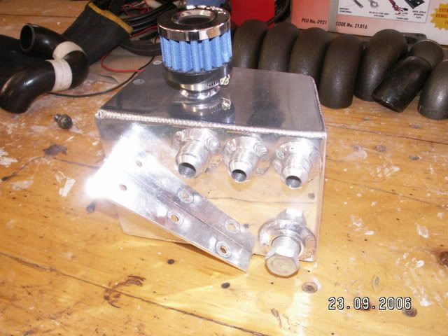
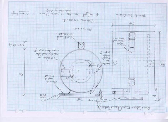
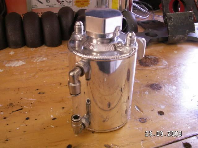
I had decided that the Starlet might need some bling. So I decided to design an oil catch can for the engine bay. It would sit above the drivers side tower. The design was very unorthadox, but looked very good in the end. Once again, Paul Denooyer from P&F Fabrications did the work. here is the drawing I sent him.
Image

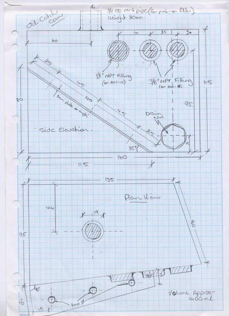
And this is what came back - 'BLING'....
Image

Next in Chapter 7 - We finish off the engine bay and tie it all together (and add a bit more 'bling' besides).....

_________________
"Not Speeding Officer..........Qualifying"


Top
 Profile  
 
 Post subject:
PostPosted: Fri Sep 29, 2006 11:45 am 
Offline
848cc
848cc
User avatar

Joined: Tue Apr 12, 2005 3:58 am
Posts: 426
Location: On a mission...
One of the things that is most remarkable things about this build, is the fact you have a full time job & 2 kids! :shock:

Nice rad by the way 8)

_________________
Metal to burn, sparks to fly...


Top
 Profile  
 
 Post subject:
PostPosted: Fri Sep 29, 2006 8:40 pm 
Offline
998cc
998cc
User avatar

Joined: Wed Jul 20, 2005 8:23 pm
Posts: 776
Location: Concord West, NSW
Fantastic update, I agree about the planning, I spent many a nights and days thinking about how to do things before i actually attempted them.

One thing i found by mounting my coil pack in the same location is that i have been unable to locate a longer coil lead, note the fittings are not the standard 8mm type. I have been advised that a company may be able to make them to size in Penrith???

DAN


Top
 Profile  
 
 Post subject:
PostPosted: Sat Sep 30, 2006 11:50 am 
Offline
998cc
998cc
User avatar

Joined: Thu Aug 03, 2006 9:00 pm
Posts: 536
Location: Sydney
MAKE SURE YOU CHEK VOLTAGE WHEN USING A ALLUMINIUM RAD!!!!! otherwise you will get a hole in the rad real fast.... We did it at work on a HG prem and with the car sitting there not moving in a matter of 4 weeks she sprang a leak...... NO CRAP.. It turns out we didnt have anough earths on the car and current was running through the coolent reacting with the alloy radiator and causing electrolisis make a hole in the rad $5oo bucks down the drain... We did some checking and turns out you have to have as many eaths as you can get... Check the currnt in the coolent by placing a volt meter in through the cap hole, dont touch the radiator with the tip though... Current shepuld be dont to 0.5 volts.... We were told that much higher then this and you have a hole.... Ours was 3 volts... Do this with the battersy in and the car all wired up.... Keep this is mind....

Mike

_________________
If it cant be fixed with a hammer it cant be FIXED!!


Top
 Profile  
 
 Post subject:
PostPosted: Sun Oct 01, 2006 12:24 am 
Offline
1275cc
1275cc
User avatar

Joined: Thu Jun 03, 2004 2:56 pm
Posts: 3981
Location: Brisbane
AT is a sparky by trade........

_________________
But he's thriving and striving and hugging the turns.


Top
 Profile  
 
 Post subject:
PostPosted: Sun Oct 01, 2006 7:49 am 
Offline
1275cc
1275cc
User avatar

Joined: Fri Jun 17, 2005 10:31 am
Posts: 3183
Location: Burpengary, Queensland - Home of Tricky Performance Engineering
Hi Mike,

Very good point.

Transient currents can cause immense damage with eletrolysis and galvanic reaction.

I thought of this when I designed the radiator.

If you notice the drivers side mounting points, they are just a flat bar that will be drilled and then mounted solidly onto the slam panel mid-brace.

The passenger side however, has grommet openings cut into them (pic one above). This side will be mounted via rubber grommets and wont ever touch the body work.

Since electrical current will always take the route of least resistance, any transient currents cannot flow from one side of the radiator to the other. i.e. there is no path of continuity across the radiator to create a potential difference.

Cheers,
Tricky

_________________
"Not Speeding Officer..........Qualifying"


Top
 Profile  
 
 Post subject:
PostPosted: Mon Oct 02, 2006 4:34 pm 
Offline
998cc
998cc

Joined: Sun Apr 03, 2005 3:10 pm
Posts: 891
Location: Brisbane, West Siiede
looks great

after just being at delta mini shop and seeing the price of the Kad Twin Cam engine bang for buck the conversion wins hands down


Top
 Profile  
 
 Post subject:
PostPosted: Wed Oct 04, 2006 7:36 pm 
Offline
1275cc
1275cc
User avatar

Joined: Fri Jun 17, 2005 10:31 am
Posts: 3183
Location: Burpengary, Queensland - Home of Tricky Performance Engineering
marcsvenson wrote:
looks great

after just being at delta mini shop and seeing the price of the Kad Twin Cam engine bang for buck the conversion wins hands down


Thanks Marc - look forward to having yours in the shop if you are still keen!!

Cheers,
Tricky

_________________
"Not Speeding Officer..........Qualifying"


Top
 Profile  
 
 Post subject:
PostPosted: Wed Oct 04, 2006 9:28 pm 
Offline
1275cc
1275cc
User avatar

Joined: Fri Jun 17, 2005 10:31 am
Posts: 3183
Location: Burpengary, Queensland - Home of Tricky Performance Engineering
Chapter 7 - Finishing the Engine Bay

OK, the motor is in, subframe passed by the engineer. But, there is still a swag of stuff to go into the engine bay. Its all got to go into logical positions that will work favourably with the other equipment around it.

Dan made a good point about planning - he put his coil pack in a logical position, only to find that the HT lead did not reach (sorry Dan!). Fortunately my lead did reach. Dan we need to get together and see if there is differing lengths between Starlet models.

Ok, lets talk about brakes for a second. Obviously a very important part of the conversion as a whole. In my proposal that was sent to the Ginger Beer (Engineer), QBR suggested using the metro setup for the front brakes, with a booster, and up-rating the rear brakes to Superfins (1.5" wide shoe rather than 1.25"std). this was well recieved, but hardly anything new or radical.

Now the metro setup uses 8.4" (213mm) ventilated disks with 4-pot opposing calipers. However, QBR also suggested using a tandem master cylinder with proportioning valve to allow for front-rear bias due to load. Nothing new here either really. Its just a matter of cramming all this stuff in.

As most of you know, you must turn the brake master cylinder around 180 deg. to be able to get the Starlet engine in without it fouling on the brake master cylinder. Easy. I decided to locate the proportioning valve to the left (drivers side) of the master cylinder. I had an opning in the firewall for the electrical wiring to come through on the other side of the master cylinder, so that was out.

The clutch master cylinder can stay in the std location, although I had to remove a 1/4" vacuum fitting from the inlet manifold so it wouldnt foul on the clutch master cylinder. I plugged this hole with a 1/4" allen key grub screw. Also of interest is the oil filter. I purchased a remote oil filter relocation kit from Earl's Performance products in Sydney (great guys!). It cost me $230 including 4 speedflow fittings for the hoses. I decided to mount this right side up in front of the oil catch can for the following reasons:
1. It was high up so would back-drain into the sump
2. Easy to spin new filters on and off
3. Away from stones and other flying debris
4. Was close to where I am going to mount the oil cooler (which replaces the TMIC) in stage II
5. There are already a bunch of vacuum hoses along the route between the original oil filter position and the new one so I had somewhere to clamp the new hoses to.

Here is a pic of the oil catch can in position. As I said, the shape is unorthadox, but it fits the position perfectly Behind it, is the proportioning valve for the front/rear brake biasing. In front is the new oil filter relocator.
Image

Now that everything was in place with regards to the brakes, it was time to run all the solid brake lines. I bought a pipe bender, and cut-off tool and about 5m of brake bundy tubing. This was a long and labourious process. I would not want to inflict this on anyone. Do your self a favour - go and see Midas!!!
Here is a front on of the engine bay, with all the equipment in, less the air filter box and radiator. Crowded isn't it?
Image

Notice the two holes in the firewall for the electrical cabling to come through. They are the same size as what was in the starlet firewall. The fuse box and relay holder, as well as ECU etc will all be behind the dash (more on this later!).

This is a shot from the drivers side. Notice how the brake lines run behind everything else:
Image

And from the passenger side. The booster has got its lines, as has the clutch:
Image

And here's a tip. I kept all the brake line plastic clips and mounts to reuse on the Mini. They became invaluable to making the job look nice and neat! I wanted to make the engine bay look as modern as I could. To this end I decided to replace the bonnet opening prop with gas struts. This would make it easier to work on as well!! Down the wreckers I went, and for $30 came back with a pair of VR Commodore gas struts. They fitted like they were made for the Mini. They have a nice long travel, so the bonnet isnt too hard to pull down and doesnt shoot up out of control!
Image

So, thats about it for the engine bay. All thats left to do is the electrics, the feed air pipe from the air-box, and some oil, fuel and water lines. Also,lets not leave out painting. All the brackets, intercooler pipes and fittings will be light blue, to contrast the Dodge Viper Blue of the valve cover and engine bay. Should work well I hope.

Something I should mention. I made an error that cost me some bucks because I was stupid!!. I had decided to get fabricated a custom radiator overflow bottle. So, after taking some dimensions, I came up with the following drawing which I sent to P&F Fabrications to get made up:
Image

And here's what came back - perfect!! It is to be mounted on the passenger side guard in front of the air filter box.
Image

Only thing is, I forgot to take into acount I had instructed Paul to relocate the filler neck on the radiator closer to the passenger side to ensure that there would be no interference for a thermo fan. This relocation then forced the overflow bottle lower than expected which clashed with the filter box oulet pipe. Oh well, best laid plans of mice and men!! Should have done more forward planning and less drawing!

Next in Chapter 8 - Join me as we go on a spending spree in the UK!!

_________________
"Not Speeding Officer..........Qualifying"


Top
 Profile  
 
 Post subject:
PostPosted: Thu Oct 05, 2006 8:33 am 
Offline
998cc
998cc
User avatar

Joined: Sun Jun 11, 2006 2:15 pm
Posts: 604
Location: caboolture qld
great mate looks awsome

_________________
Cheers Dan

FIRST COMES THE MONEY, THEN COMES THE POWER, THEN COMES THE WOMEN.!!


Top
 Profile  
 
 Post subject:
PostPosted: Thu Oct 05, 2006 2:35 pm 
Offline
998cc
998cc
User avatar

Joined: Wed Jul 20, 2005 8:23 pm
Posts: 776
Location: Concord West, NSW
Mateeee!! That looks great, i wish my engine bay was that big. Imade my own brake lines too and i agree, if possible get someone else to do it.

Dan


Top
 Profile  
 
 Post subject:
PostPosted: Thu Oct 05, 2006 5:01 pm 
Offline
ET 13.457 seconds , OH YEAH !!!!
User avatar

Joined: Sun Sep 19, 2004 8:35 am
Posts: 7826
Location: Somewhere Around Sydney
minimetoy wrote:
Mateeee!! That looks great, i wish my engine bay was that big. Imade my own brake lines too and i agree, if possible get someone else to do it.

Dan


Hehe so much more room in a clubby :D

Nice work Tricky 8)

Dan..i'll give you a call tonight or tommorow ;)

_________________
Image
Starlet Conversion:
http://www.ausmini.com/forums/viewtopic.php?t=15484


Top
 Profile  
 
Display posts from previous:  Sort by  
Post new topic Reply to topic  [ 1864 posts ]  Go to page Previous  1, 2, 3, 4, 5, 6, 7 ... 125  Next

All times are UTC + 10 hours


Who is online

Users browsing this forum: No registered users and 33 guests


You cannot post new topics in this forum
You cannot reply to topics in this forum
You cannot edit your posts in this forum
You cannot delete your posts in this forum
You cannot post attachments in this forum

Jump to:  

© 2016 Ausmini. All garage work involves equal measures of enthusiasm, ingenuity and a fair degree of irresponsibility.