Ausmini
It is currently Tue Mar 19, 2024 4:10 pm

All times are UTC + 10 hours


Post new topic Reply to topic  [ 413 posts ]  Go to page Previous  1 ... 12, 13, 14, 15, 16, 17, 18 ... 28  Next
Author Message
PostPosted: Sun Jun 05, 2016 9:45 am 
Offline
848cc
848cc

Joined: Fri Jan 02, 2015 9:01 am
Posts: 483
Location: Perth, W.A.
Your attention to detail is outstanding! I reckon your mini is going to turn out superbly. I look forward to the build.


Top
 Profile  
 
PostPosted: Fri Aug 26, 2016 9:52 pm 
Offline
998cc
998cc
User avatar

Joined: Tue Nov 13, 2007 4:17 pm
Posts: 946
Location: NOR, Perth, W.A.
All fabrication and set up in the workshop is now complete and I am extremely happy the final set up & features, layout and how much spare room I have to move around everything. The last few things to sort out was water supply, steel & fastener storage racks, paint booth, air supply items.

So am I ready to get started on the Mini again? In spirit, yes. In real life, no. I have some final house renovation tasks I have to complete before I can, however the next update here should be BUILD related but by then it will be very close to FOUR YEARS since I last worked on it :cry:

Air Supply : I upgraded my little 10 year old Super Cheap 2hp compressor to a 3hp belt driven (3.2CFM vs 11CFM air flow) as I'm considering doing some small sand blasting jobs and the small compressor will never keep up. Get a belt driven compressor - they are wonderfully quiet compared to the direct drive models. I have also installed Nitto Hi Cupla quick connect fittings around the workshop perimeter. These fittings make it an easy one handed job to insert or release hoses and I have 2 outlets over the workbench and 4 others around the perimeter of the workshop.
Image

Image

Fasteners Storage : After stripping 2 Minis, a Starlet half cut and various other bits from house reno & workshop, I've accumulated a sh!t load of nuts/bolts/screws/clamps etc, I needed to organise everything. I used an ex-work A4 paper storage tower and fabricated a heap of drawers for them. Smaller fixings were stored in some plastic storage containers with everything else in various combinations of MDF drawers storage section sizes. I panted the fascias the same colour as everything to match.
Image

Image

Steel Storage : I also didn't realise how much steel tube & pipe I had accumulated so I figured storing everything vertically will take up a very small footprint. This rack was welded up from leftover SHS steel lengths and is raised to fit a wheeled storage container underneath for smaller pieces
Image

Image

_________________
-Alan
I blame my dad for my love of minis. I think I was conceived in the back seat of one :D
I also blame my Dad for me being 6' 1" - not really the optimum height for driving a Mini.


Last edited by Mearcat on Sat Aug 27, 2016 12:22 am, edited 5 times in total.

Top
 Profile  
 
PostPosted: Fri Aug 26, 2016 10:01 pm 
Offline
998cc
998cc
User avatar

Joined: Tue Nov 13, 2007 4:17 pm
Posts: 946
Location: NOR, Perth, W.A.
Paint Booth : After wiring up the switches for interior light, fan & the compressor, I installed a basic pine/MDF bench with some drawers to store materials. I jumped on my wifes sewing machine and made some simple curtains to stop overspray getting on the compressor & drawers. The filters were made from 2nd hand flyscreen frames that I cut down and installed air-conditioning filter medium (grey colour) for dust particle separation on inlet. The outlet filter material (not shown in pics) is a finer grade to capture paint overspray dust. A little bit of luxury was added with some ex-office carpet tiles :)
Image

Image

Image

Image


Water Supply : The workshop has everything including a sink :) Between the paint booth and workbench, I made another simple pine frame to hold the sink. The water is supplied from a 220L drum (filled from the workshop shed rainwater downpipe) and a 12V caravan low flow pump (4L/min) powered by a laptop power supply. I have a IP56 rated switch on the right of the sink to turn the pump on/off. The waste outlet pipe for the sink was already installed when the slab was poured.
Image

Image

_________________
-Alan
I blame my dad for my love of minis. I think I was conceived in the back seat of one :D
I also blame my Dad for me being 6' 1" - not really the optimum height for driving a Mini.


Top
 Profile  
 
PostPosted: Mon Feb 20, 2017 10:40 pm 
Offline
998cc
998cc
User avatar

Joined: Tue Nov 13, 2007 4:17 pm
Posts: 946
Location: NOR, Perth, W.A.
So after over 4 years of not working on the Mini thanks to a house renovation/extension/owner-builder projects, I'm finally back into it :D I've decided to restart the project by building up the rear subframe, making new brake lines (custom ones thanks to me using a Minispares adjustable bias valve mounted in the rear subframe), assembling Hi Los etc. About 6 years ago (before I had the skills to do it myself), I had a local guy do some various body panel repairs which included replacing the rear valance and part of the boot floor, and he did a woefully sub-quality job of everything (I had to get a second guy fix some of those issues) but it has now come back to bite me...

After the trunnions/bushes were assembled on the subframe, I bolted the front trunnions onto the body to see if the holes for the rear trunnions lined up. None of them did. The LHS pair of body holes was 3mm out of alignment (easy fixed), but the RHS pair of holes was 9mm too far towards to centreline of the car. What a balls up :evil: :evil: . I'll now have cut out part of the boot floor as weld it back in the correct position. My concern after the subframe is whether the boot lid will even fit!

_________________
-Alan
I blame my dad for my love of minis. I think I was conceived in the back seat of one :D
I also blame my Dad for me being 6' 1" - not really the optimum height for driving a Mini.


Last edited by Mearcat on Sun Apr 02, 2017 12:33 am, edited 4 times in total.

Top
 Profile  
 
PostPosted: Tue Feb 21, 2017 7:43 am 
Offline
998cc
998cc
User avatar

Joined: Fri Jan 28, 2011 1:19 pm
Posts: 533
Location: Adelaide
That's a pretty special workshop mate

_________________
Zulu...

1967 mini Cooper S


Top
 Profile  
 
PostPosted: Tue Feb 21, 2017 8:28 am 
Offline
Give Ash some flowers Nick .
User avatar

Joined: Wed Aug 09, 2006 1:22 pm
Posts: 10149
Location: Toowoomba Region, QLD
Glad to hear you are getting back into it. The workshop is turning out well. You've had some good ideas that I think I'm going to straight out steal (if that's ok) for my new shed / workshop. I love the drum with the caravan pump in it - great thinking!

_________________
"In two years time your car will be like a lady's clothes, out of date, my car will still be in fashion when I am dead" - Sir Alec speaking to Pininfarina


Top
 Profile  
 
PostPosted: Sun Apr 02, 2017 12:47 am 
Offline
998cc
998cc
User avatar

Joined: Tue Nov 13, 2007 4:17 pm
Posts: 946
Location: NOR, Perth, W.A.
The fix of my rear subframe alignment has now been fixed. I ended up cutting some small round pieces of 5mm steel, welded into the holes and drilling the new holes and grind back the welds.

For reference to how bad it was, the ruler in the pic below shows the centreline of the standard holes thanks to the crappy repairs that were already done prior.
Image

Image

Image

I could finally get around to assembling the subframe and the rear brakes lines had to all be redone. The cheapish flaring tool I used to have could produce good flares but it was just really inconsistent in the quality from flare to flare so I upgraded to an Eastwood on-car flaring tool (surprisingly only about $70), designed for doing flares on brakes lines whilst still attached to the car. This new tool consistently produced very nice clean and even flares (both bubble & inverted) and the kit has a removable handle which is perfect for holding the main piece in the vice.
Image

Image

For the rear subframe, I ditched the standard T piece and will be using an adjustable bias valve so the front/rear bias can be adjusted once the system is fully plumbed in. The bias valve bracket that I welded (and tapped with a 3/8" UNF hole) to the subframe was positioned specifically to avoid fouling against the handbrake cable. This all meant the usual custom work for the lines from the front of the car to the valve; and valve to radius arms. A pair of lines were also bent up for the radius arms.
Image

Image

From there, the radius arms were filled with lithium grease and bolted onto the subframe and the Hi-Lo suspension kit trial fitted.
Image

_________________
-Alan
I blame my dad for my love of minis. I think I was conceived in the back seat of one :D
I also blame my Dad for me being 6' 1" - not really the optimum height for driving a Mini.


Last edited by Mearcat on Sun Apr 02, 2017 9:30 pm, edited 2 times in total.

Top
 Profile  
 
PostPosted: Sun Apr 02, 2017 8:29 pm 
Offline
998cc
998cc
User avatar

Joined: Tue Nov 13, 2007 4:17 pm
Posts: 946
Location: NOR, Perth, W.A.
I purchased a K-Mac sway bar kit several years ago and while assembling the rear subframe on the workbench, it was the appropriate time to fit it. I unboxed everything and found that the link brackets (that bolt to the of the radius arm backing plate) supplied with the kit were very low quality so I decided to replicate them to a higher standard.
Image

Image

The other part of the kit that concerned me was the spacer used between the pairs of link bushes and retaining washers looked like it was made from scrap thin wall tube. I have no practical knowledge of whether this is actually a concern, so to put my mind at ease I machined up some much thicker spacers on the lathe to match the diameter of the bolt head & nut.
Before & After :
Image

That is where things went south. I should have attempted to fit the sway bar before making the new brackets because they cause the link bolt assembly to be mounted right in way of where the handbrake cable spring is supposed to run. There was no way the handbrake cable and spring would fit with this configuration. Seriously? Who designed this and thought it was acceptable?!
Image

The swaybar itself was not the best quality either, bent 20mm too narrow so the sway bar holes didn't even line up with the link bracket holes (one side of the bar was bent at 81deg and other side at 89deg) and as well has a twist in it so that when I sat it on the ground, one side sat ~10mm above the other side! If I had not of purchased this kit over 4 years ago, I'd be sending it back for a full refund.

So after fair bit of pushing, pulling, leverage and twisting in the vice later, I had the bends suitable so the links will clear everything, and no twist either. It's time to sit and stare for a while at the setup pictured below and design a brand new link bracket that also clears everything...
Image

_________________
-Alan
I blame my dad for my love of minis. I think I was conceived in the back seat of one :D
I also blame my Dad for me being 6' 1" - not really the optimum height for driving a Mini.


Top
 Profile  
 
PostPosted: Sun Apr 09, 2017 11:35 pm 
Offline
998cc
998cc
User avatar

Joined: Tue Nov 13, 2007 4:17 pm
Posts: 946
Location: NOR, Perth, W.A.
So to make the new sway bar link bracket I needed of course to make sure nothing around it fouled on the bracket, and make sure it was strong enough. Because I had the subframe on the workbench, I didn't know the "normal" position/angle of the radius arms compared to the subframe. I measured up a friends standard height Mini and made sure mine was the same on the bench. The reason for this measurement is that I wanted to perform the sway bar install as if the car was in a neutral suspension position. I went through 3 iterations of a new bracket design in both cardboard and steel before deciding on one I felt best - for both clearance and strength.

I wanted the sway bar to be parallel with the radius arm (and the link bracket to perpendicular to sway bar and radius arm) so the link bushes wouldn't have any additional load in normal driving conditions. I measured the angle 12.1°
Image

I propped up the sway bar to that angle, made some measurements and fabricated a pair of link brackets (and also another pair for a local Mini club member who had the same style sway bar). The bracket slides over the shock absorber stud on the radius arm and is made of 30x5mm flat steel bar and custom bolt (machined on the lathe). The 5mm thick gusset fully welded down one side strengthens the whole bracket and also helps to transfer the vertical load to the stud. It will still need to be cleaned up (sand blasted) and painted.
Image

At this point I also had to tweak the bend angles of the sway bar (in the vice) to match up with where the link bracket bolts were. Once installed, I measure the angle of the sway bar and at 11.3°, I was impressed that I managed to achieve within 1 degree of the radius arm.
Image

From there, holes for the bush saddles were drilled and everything bolted in. As I expected, the brake lines I recently made fouled against the new brackets so I will have to remake those, but that's not a big job. The (mostly) assembled subframe will now be put aside to move onto something else.
Image

Image

_________________
-Alan
I blame my dad for my love of minis. I think I was conceived in the back seat of one :D
I also blame my Dad for me being 6' 1" - not really the optimum height for driving a Mini.


Top
 Profile  
 
PostPosted: Mon Apr 10, 2017 7:06 am 
Offline
1098cc
1098cc

Joined: Sat Jul 23, 2011 8:17 am
Posts: 1964
Location: san remo nsw
I remember the Selby bar I had on a Mini, years ago, the link was just a bolt with a washer welded on it, lined up with shock stud ok but went on inner (nut) end. not very good engineering.


Top
 Profile  
 
PostPosted: Mon Apr 17, 2017 6:06 pm 
Offline
998cc
998cc
User avatar

Joined: Tue Nov 13, 2007 4:17 pm
Posts: 946
Location: NOR, Perth, W.A.
The rear subframe is nearly ready to put aside but the last task was to mount a fuel filter. I chose a Ryco Z354, suitable for a various model EFI Toyota Corollas including the 100kW version and I see no reason why it wouldn't be suitable for the 100kW+ 4E-FTE also. It also has the mount bracket integrated into it so I didn't have to fabricate a mount. I simply installed two M6 rivnuts in the side of the subframe and bolted in on

Image

The shell still had some bitumen-based body deadener/sealer on the underside of the boot from when the body work done many years ago and had a replacement boot floor welded in. So heat gun, paint scraper, wire wheel and an hour later I found a few pin holes in the boot floor which ended up being more than pinholes. I cut out several small pieces and welded in new sections. I also spent some time with a flap disk cleaning up some "bird-poo" welds from the previous repair.
Image

Image

While the sway bar was bolted in, I offered up the muffler in it's approximate position and I wasn't happy with the proxmity of the muffler to the brake line so I remade it. The line now runs from the bias valve and runs directly under the valve to the instead of the original route which went around the side of the valve and past the adjustment wing nut.
Image

_________________
-Alan
I blame my dad for my love of minis. I think I was conceived in the back seat of one :D
I also blame my Dad for me being 6' 1" - not really the optimum height for driving a Mini.


Top
 Profile  
 
PostPosted: Mon Jun 12, 2017 1:45 pm 
Offline
998cc
998cc
User avatar

Joined: Tue Nov 13, 2007 4:17 pm
Posts: 946
Location: NOR, Perth, W.A.
Some recent updates :

I've updated the VH44 brake booster mount / bracket to include a strengthening top piece which molds around the shape of the booster cylinder.
Image

I've bought and set up a small sand blasting cabinet from one of recent sales at Super Cheap Auto. Out of the box, the lighting is woeful so I've replaced the measly 6W flouro with four long strips (16W total) of 5050 SMD LED strips which make a night & day difference. I also installed a small cyclone system between the cabinet and my workshop vacuum cleaner which so far has been incredibly efficient in collecting the really fine dust that is produced from blasting. After that, the cabinet was a great little home-use cabinet. They do use a LOT of air so even my 13CFM belt drive compressor only just keeps up.
Image

I have cut out the factory radiator slots and replaced it with some sheet metal to prevent any ingress of water, stones etc etc into the engine bay. The airbox mounts in this position so some rivnuts were place in the sheet to mount it.
Image

The concern of heat soak in the engine bay has weighed on my mind a lot. In an attempt to reduce the heat from the exhaust parts being transferred to the intake piping above it (as well as other engine bay components), I previously had the exhaust manifold ceramic coated and then made a heat shield for the manifold from 0.8mm steel sheet but I wanted something that would actually cut down radiant heat so I ditched the steel cover and made a shield for the exhaust manifold and turbo from proper heat shield material.

Exhaust Manifold cover :
Image

Turbo cover (using 2x factory bolt holes for mounting) :
Image

Both installed :
Image

_________________
-Alan
I blame my dad for my love of minis. I think I was conceived in the back seat of one :D
I also blame my Dad for me being 6' 1" - not really the optimum height for driving a Mini.


Top
 Profile  
 
PostPosted: Sat Jun 17, 2017 10:32 am 
Offline
1098cc
1098cc
User avatar

Joined: Sat Feb 22, 2014 10:13 am
Posts: 1362
I also installed more LED strips like you, they work a charm! Those heat shields look excellent, well done.

Sent from my Nexus 6P using Tapatalk

_________________
Build thread for Supercharged 1275 1967 Deluxe Resto
Build thread for Mini ute conversion 998cc Turbo


Top
 Profile  
 
PostPosted: Mon Jul 17, 2017 12:20 pm 
Offline
998cc
998cc
User avatar

Joined: Tue Nov 13, 2007 4:17 pm
Posts: 946
Location: NOR, Perth, W.A.
I have not fitted the front subframe in the shell for over 4 years and when I recently tried to fit it, I found that there was a significant change somewhere in subframe compared to the shell. A few holes in the subframe did not line up with the holes in the front apron panel, the brace bar across the front of the subframe would not bolt on to the front mount plates. The subframe main spars (running forward from from top of the towers) had likely been damaged in transit while moving house a few years ago and it has gone unnoticed until now. Not a lot of damage but just enough for holes to no longer line up :(

I don't have any thing big or strong enough to bend things back into place so I had no choice but to cut off the front of the subframe and weld things back together where they were supposed to be.
Image

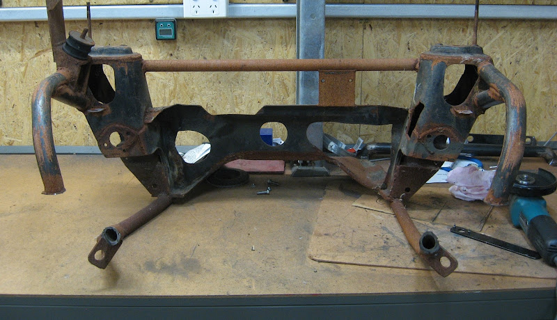
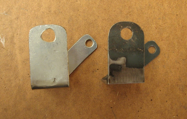
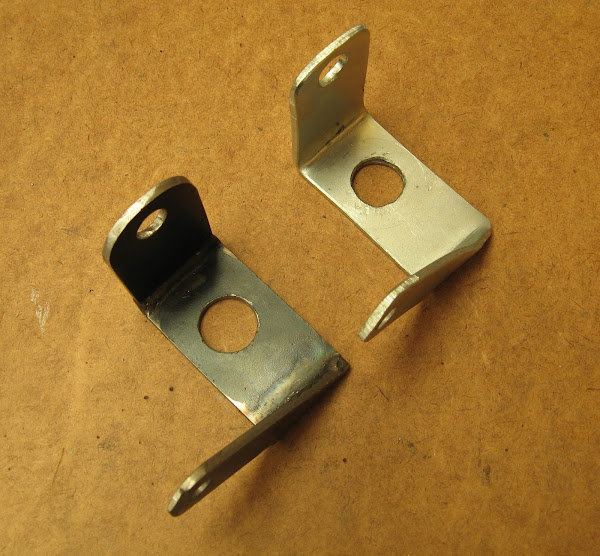
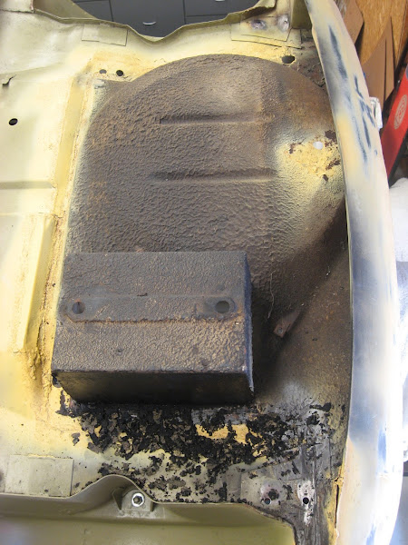
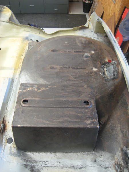
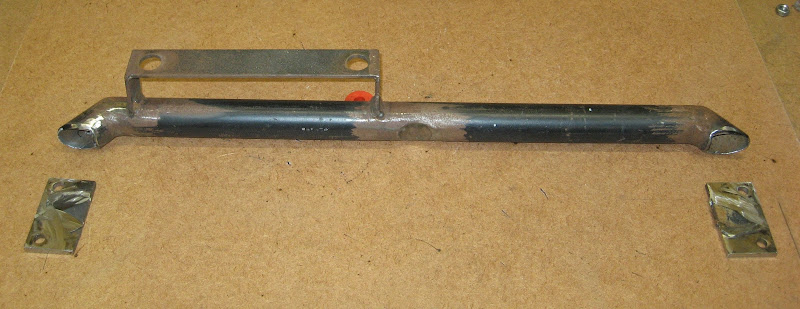
Front brace bar with mounts cut off :
Image

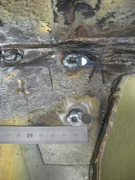
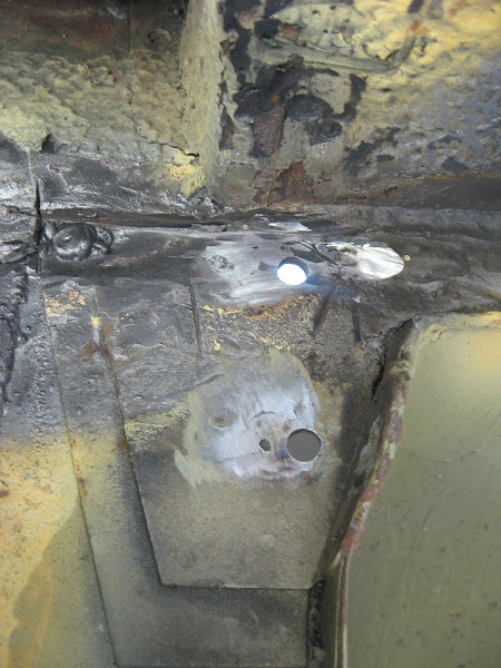
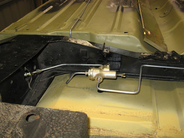
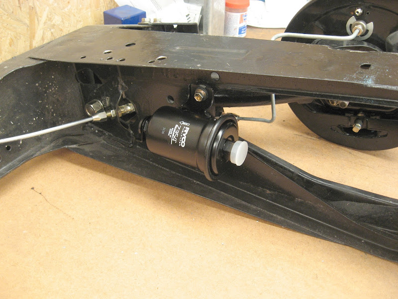
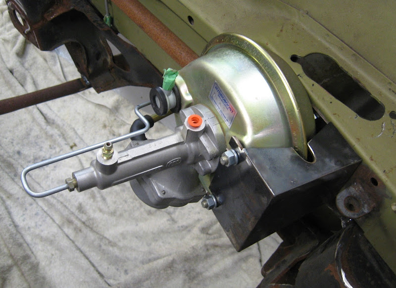
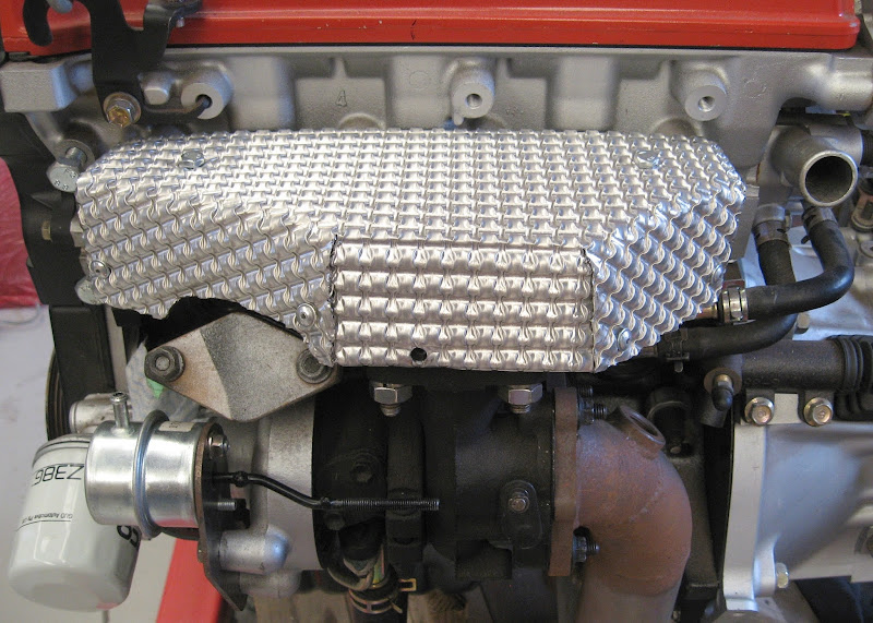
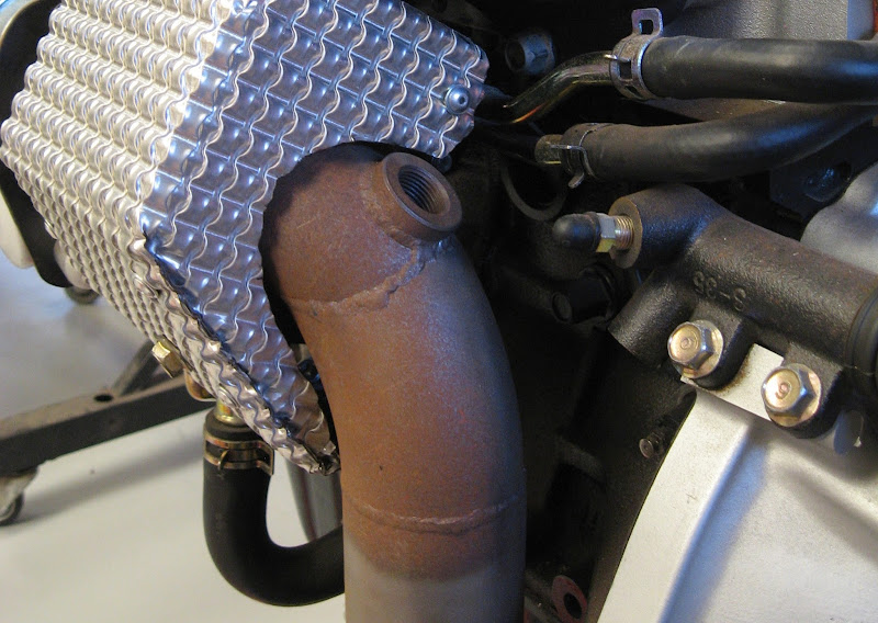
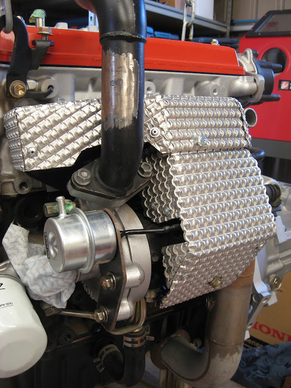
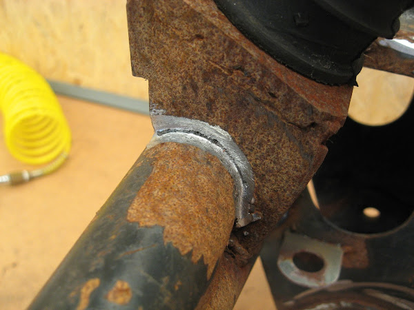
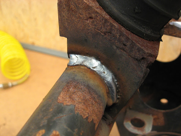
While cutting some of the pieces off, a very small volume of water ran out of one of the pipes. The subframe had been stored out in the elements over an entire winter so not only was it covered in surface rust, a pinhole in a weld had allowed ingress of some water. I decided to inspect all of the welds I had done previously (with a stick welder) and grind back a lot of the welds with a die grinder and redo them with my MIG. The subframe and engine are now installed so I can continue with engine-bay related items.
Image

Image


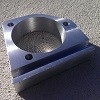
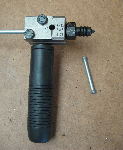
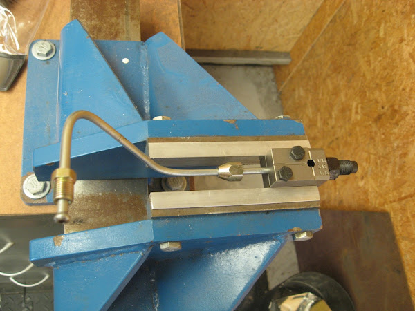
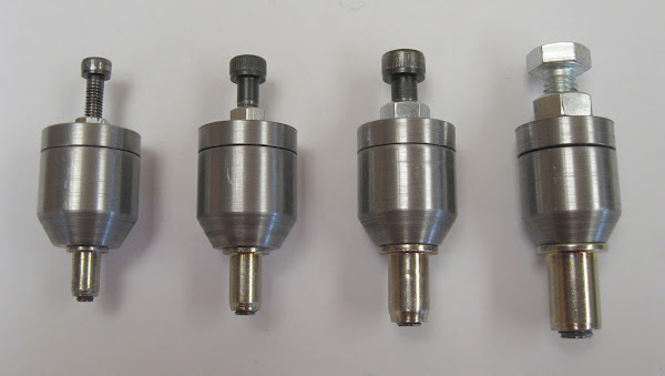
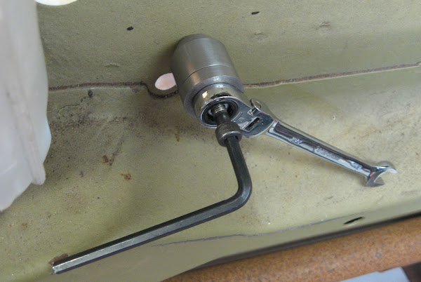
I have also been doing a bit of work on the lathe lately, making some DIY rivnut tools (after my cheapy rivnut tool broke while attempting to install a bigger M8 rivnut). These are easy to use and make light work of installing rivnuts/nutserts with the thrust bearing in them :
Image

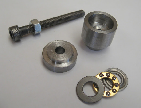
One tool for each size M4-M8
Image

Image


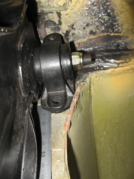
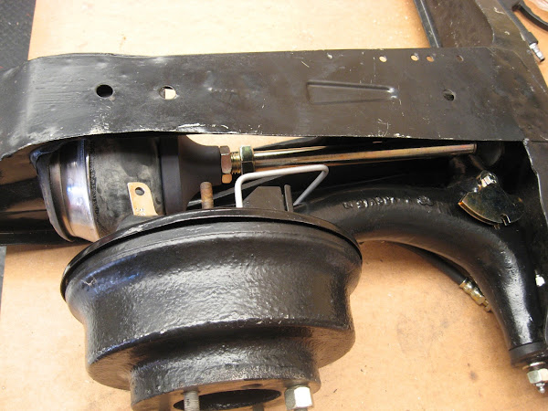
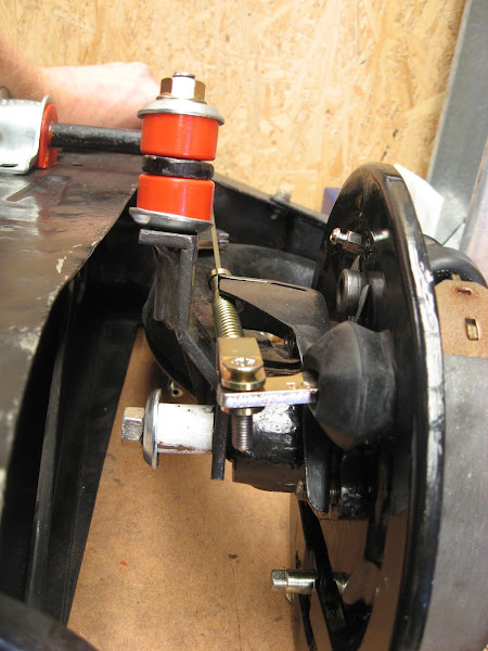
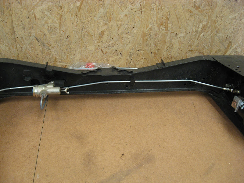
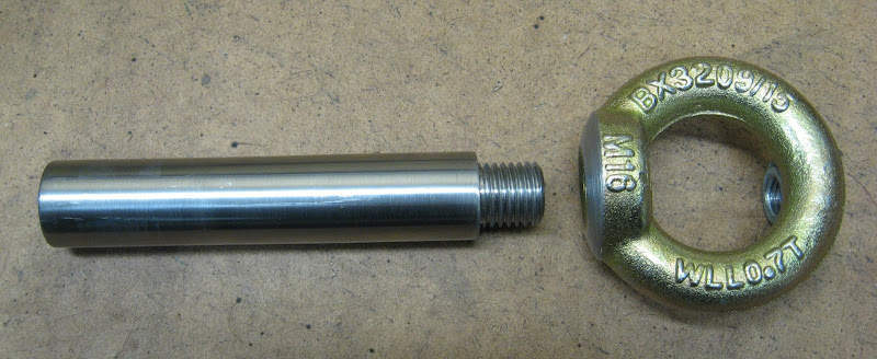
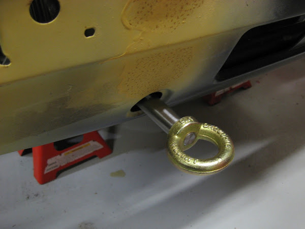
After a mate of mine snapped a driveshaft on his Mini at the drags recently, I figured I'd need a tow ring at some point to tow/move the Mini around even before it's registered. This was a simple job, made from a 700kg-rated lift eye and some tapped/threaded 20mm steel rod. I increased the subframe front bolt size from 5/8" to 1/2" and installed a longer threaded bolt for the tow ring to screw onto. I'll also install a 1/2" captive nut in the rear subframe at a later time so the tow ring can be fitted at the rear too.
Image

Image

_________________
-Alan
I blame my dad for my love of minis. I think I was conceived in the back seat of one :D
I also blame my Dad for me being 6' 1" - not really the optimum height for driving a Mini.


Top
 Profile  
 
PostPosted: Mon Jul 17, 2017 1:16 pm 
Offline
998cc
998cc
User avatar

Joined: Fri Jan 28, 2011 1:19 pm
Posts: 533
Location: Adelaide
Mearcat wrote:
I measured the angle 12.1°...
Image


"Make the noise...."

_________________
Zulu...

1967 mini Cooper S


Top
 Profile  
 
Display posts from previous:  Sort by  
Post new topic Reply to topic  [ 413 posts ]  Go to page Previous  1 ... 12, 13, 14, 15, 16, 17, 18 ... 28  Next

All times are UTC + 10 hours


Who is online

Users browsing this forum: No registered users and 5 guests


You cannot post new topics in this forum
You cannot reply to topics in this forum
You cannot edit your posts in this forum
You cannot delete your posts in this forum
You cannot post attachments in this forum

Jump to:  

© 2016 Ausmini. All garage work involves equal measures of enthusiasm, ingenuity and a fair degree of irresponsibility.