Ausmini
It is currently Tue Mar 19, 2024 8:43 pm

All times are UTC + 10 hours


Post new topic Reply to topic  [ 413 posts ]  Go to page Previous  1 ... 14, 15, 16, 17, 18, 19, 20 ... 28  Next
Author Message
 Post subject:
PostPosted: Mon Dec 18, 2017 5:09 pm 
Offline
998cc
998cc
User avatar

Joined: Tue Nov 13, 2007 4:17 pm
Posts: 946
Location: NOR, Perth, W.A.
The engine now has a catch can. There are two breather ports in the 4E valve cover - one normally leads to the recirculation valve and one is a PCV valve. I'm replacing the factory recirc valve with a Turbosmart one and the PCV valve was faulty (was allowing air flow both ways) so I decided to the PCV system and replace it with a catch can - a Provent. I use one of these in my diesel 4WD and it's quite effective and they have a really small model ~150mm high & 100mm diameter.

To join both valve cover ports to the Provent filter, and using off-the-shelf hose adapters and pieces to join all the sizes of outlets it was going to a mess of so I made some custom adapters myself. I used some HDPE rod and machined some pieces to make a Tee and 90 degree pieces. They are glued together with a Loctite glue specific for Polyethylene.
Image

Image

The filter has been mounted on the inner guard above the drivers side engine mount and the result is clean looking connections that doesn't look like it has just been hacked together. All fittings are a tight fit for both the hose & the valve cover ports so that there is no need for any hose clamps, although it's not a pressurised system anyway. The outlet hose from the filter is routed to a piece of 1/2" steel tube welded into the intake piping (pre-turbo). This completes a closed crankcase ventilation system where no air or vapour is vented to the atmosphere.
Image

To drain the Provent of any oil, I used a spare Fumoto valve (normally screwed into a oil sump) and made some brass adapter pieces for the drain line. This valve will be bolted to the subframe in the wheel arch.
Image

Image

_________________
-Alan
I blame my dad for my love of minis. I think I was conceived in the back seat of one :D
I also blame my Dad for me being 6' 1" - not really the optimum height for driving a Mini.


Top
 Profile  
 
 Post subject:
PostPosted: Tue Mar 06, 2018 12:47 pm 
Offline
998cc
998cc
User avatar

Joined: Tue Nov 13, 2007 4:17 pm
Posts: 946
Location: NOR, Perth, W.A.
After considering some comments made in regards to the alternator cover cooling and the fact that it was sealed from the wheel arch, I've made a duct to feed air to the alternator. Alternators with internal fans such as this one draw in air from either end of the alternator and the air is pushed out radially so with a cover over it, the alternator would not be able to get any fresh air for cooling.

I made a duct from fibreglass which picks up air from the front grille area and feeds it to the rear of the alternator via a hole in the top of the wheel arch
Image

Image

The accelerator cable has also been installed. I cut off the top of the Starlet pedal (for the cable end holder) and welded it onto the Mini pedal. The cable however was too long and had a big curve in the engine bay
Image

I had to trim 200mm off the length of the cable but the cable tension adjustment fitting was crimped on to the cable sheath. I had a remake this for the shortened sheath/cable (it's actually hidden behind the brace between the head and intake manifold once fitted)
Image

Shortening the cable also meant having to cut off the barrel nipple on the end of the cable. I made an adjustable barrel nipple (aka barrel clamp, cable end) from brass with a 2.5mm hole cross-drilled for the accelerator cable to pass through, and threaded for a small bolt to clamp the cable in place.
Image

The shortened cable
Image

New adjustable barrel nipple in the throttle body quandrant :
Image

The Starlet (as well as most cars) has a return spring fitted to the accelerator pedal and from the experience of Rob here in Perth and his 4E-FTE Mini swap, the pedal feel is rather light without it. He added a second spring on the throttle body to supplement the factory spring and I did the same
Image

Image

Lastly for now, I was getting concerned about how much the engine will move under heavy acceleration or braking, and whether this would translate into problems with things fouling with other things. To prevent any excessive movement, I considered reusing the standard Mini engine steady/stabiliser bar for the Starlet engine as it just happened to fit perfectly! One end was mounted via a bell housing bolt and a starter motor bolt and the other was mounted to the rear of the subframe.
Image

_________________
-Alan
I blame my dad for my love of minis. I think I was conceived in the back seat of one :D
I also blame my Dad for me being 6' 1" - not really the optimum height for driving a Mini.


Top
 Profile  
 
PostPosted: Wed Mar 07, 2018 10:10 am 
Offline
1275cc
1275cc
User avatar

Joined: Sun Apr 29, 2012 1:19 pm
Posts: 4331
Location: Wollongong, NSW
Looking great!

_________________
Image


Top
 Profile  
 
 Post subject:
PostPosted: Wed Apr 04, 2018 9:31 pm 
Offline
998cc
998cc
User avatar

Joined: Tue Nov 13, 2007 4:17 pm
Posts: 946
Location: NOR, Perth, W.A.
The gear shifter cables have now been finished. The gear shifter in the cabin has already been welded in the cabin so next task was to design a bracket to hold the gear shift cables onto the gearbox and cut a hole in the firewall for the two cables to pass through.

The gear shifter cables were too long for the Mini but unlike the accelerator cable, it was too complex to do the same for the shifter cables. The two cables would have to pass through the firewall on a different angle to the factory Starlet setup so I had to determine where to cut a hole in the Mini firewall. This is where my old rusty (white) Mini front cut came in very handy to determine the exact location of the hole. I measured the locations of the cables' clevis pins on the gearbox (with the engine in the good Mini shell) and replicated the locations in the white Mini using some pins at the end of steel rods and steel plates.
Image

Image

With a large opening cut into the scrap Mini firewall, the hole location was marked on the good shell and a ~40mm hole cut. I also made a custom saddle to hold the cables to the floorpan
Image

Image

To hold the cables on the gearbox, I used the factory retainer bracket which holds both cables. This was cut up for the new gear cable selector positions. Factory bracket :
Image

Modified bracket :
Image

Image

The firewall hole now had to be sealed. The rubber grommet used in the Starlet was not suitable for this new angle of the cables. I re-purposed a rubber gaiter/boot from the Mini steering rack. The larger end of the boot would be clamped to a custom mounting ring on the firewall and the two cables would pass through the small end of the boot. The only problem I had was how to stretch the small end of the boot over the cable ends and the fittings.
Image

To stretch the boot from 10mm to approx 38mm and I made a one-off tool specifically for that job. The ring has four threaded rods with a small "finger" on the end of each rod and when the outside nuts are tightened, the fingers pull the boot open so the I could easily pass the cable assembly through.
Image

Image

The mounting ring was machined on my lathe. Note : the ring has a flat section at the bottom to clear part of the subframe
Image

The position of the ring & boot between the engine and firewall made it very difficult to take a photo so I installed the setup on the old rusty Mini firewall to show how it's all put together. I used some 8mm fuel line to simulate the actual cables.
Image

_________________
-Alan
I blame my dad for my love of minis. I think I was conceived in the back seat of one :D
I also blame my Dad for me being 6' 1" - not really the optimum height for driving a Mini.


Top
 Profile  
 
 Post subject:
PostPosted: Sun Apr 22, 2018 9:49 pm 
Offline
998cc
998cc
User avatar

Joined: Tue Nov 13, 2007 4:17 pm
Posts: 946
Location: NOR, Perth, W.A.
The Mini cabin heater does a reasonable job so I will be retaining it but the Mini heater hoses are 1/2" and the Starlet heater hoses are 16mm so I needed some adapters. The standard Mini heater hoses enter/exit the cabin area through the opening at the top of the firewall and I figured that was as good a place as any to mount the adapters.

I got some 16mm tube and welded a couple of 90 degree pieces. There's no a lot of coolant volume/flow through the heater hoses so elbows should be okay.
Image

I made a pair of 16mm to 1/2" adapter pieces on the lathe welded them onto the elbows
Image

The adapter pieces were then welded to a 2mm steel plate made to be a similar shape as the original cover plate that was installed there. I felt the hoses looked a bit unfinished so I made a pair of small hose covers welded them to the tubes. The end of the hose slips into this cover and gives a nice finished look to the hose connection. I also formed some beads on the end of the tube.
Image

Another part I've been thinking about for a while is the battery wiring and I wanted to split the cable so I could install a battery cable from the boot to the firewall and then at a later date complete the engine bay wiring by simply connecting the engine bay wiring loom to a battery cable junction. Battery junction terminals are readily available but I wanted to mount one on the brace tube between the subframe towers so to make it look neater I wanted something that didn't have a flat base.

On the lathe I machined a round profile into a small rectangular block of HDPE plastic to match the diameter of the subframe brace bar. I then hand cut/filed out a hex-shaped hole and press fitted the bolt head into it, then plugged it to stop it getting pushed through.
Image
Image

With a round piece glued in place, the final product is pretty neat
Image

I drilled/tapped some holes in the brace bar to mount the terminal, and also decided that I will run an additional earth cable in parallel. Next to the battery junction terminal I drilled/tapped a thread for earth cable terminal/bolt. The 12V terminal will be covered with a battery terminal cover to prevent it getting accidentally earthed.
Image

Lastly, I have made a custom radiator overflow tank. I measured the volume of the plastic factory tank and it was 340mL so any custom tank around 300mL seemed right. I had to find a spot in the increasingly crowded engine bay to fit a tank with a volume of approx 300mL. Such a small volume meant I could squeeze something in the triangular space between the airbox duct and inner guard... just.
Image

I prototyped a design with some cardboard, then steel sheet. The steel design was sealed with some silicon and the volume measured. At 310mL, it was just about perfect. For the final product, I used 2mm aluminium plate & 8mm OD tube from a local metal supplier and an aluminium weld-on filler (25mm inlet) from eBay. I pre-cut everything and supplied all the pieces to a local guy who welded everything together for 2 cartons :D Two tabs were used for mounting the tank against the inner guard via a couple of rivnuts. Like the aluminium intercooler and radiator, I used some grommets to isolate the tank from the body.
Image

The inlet and overflow tubes are welded into the bottom of the tank to hide them and in this photo you can see the overflow tube just below the top of the tank
Image

Nice and snug in its final spot :
Image

_________________
-Alan
I blame my dad for my love of minis. I think I was conceived in the back seat of one :D
I also blame my Dad for me being 6' 1" - not really the optimum height for driving a Mini.


Top
 Profile  
 
PostPosted: Mon Apr 23, 2018 8:53 am 
Offline
1275cc
1275cc
User avatar

Joined: Thu Aug 31, 2006 7:56 pm
Posts: 2651
Location: Muswellbrook -- NSW
Some nice fabrication skills going on there , looks like they were meant to be 8) .


Top
 Profile  
 
PostPosted: Mon Apr 23, 2018 9:03 am 
Offline
1098cc
1098cc
User avatar

Joined: Thu Sep 30, 2004 3:12 pm
Posts: 1461
Location: Brisbane
Neat!
Good work!

_________________
If you want more inches, stroke it
Life's a garden.... Dig It!
http://www.ausmini.com/forums/viewtopic.php?t=20746


Top
 Profile  
 
 Post subject:
PostPosted: Mon May 21, 2018 1:15 pm 
Offline
998cc
998cc
User avatar

Joined: Tue Nov 13, 2007 4:17 pm
Posts: 946
Location: NOR, Perth, W.A.
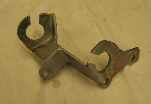
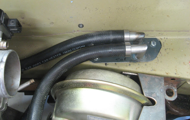
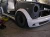
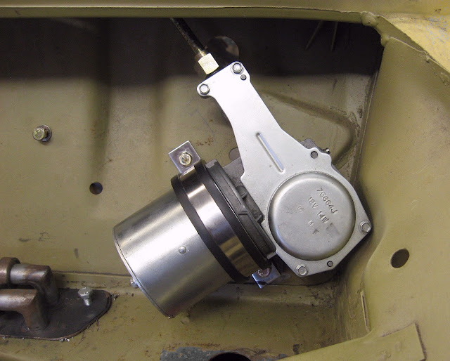
Installing the windscreen wiper mechanism has been a pain in the butt. I knew a long time ago that the old motor assembly was badly water damaged and the threads on the wheelboxes were buggered so bought new ones.
Image
Image

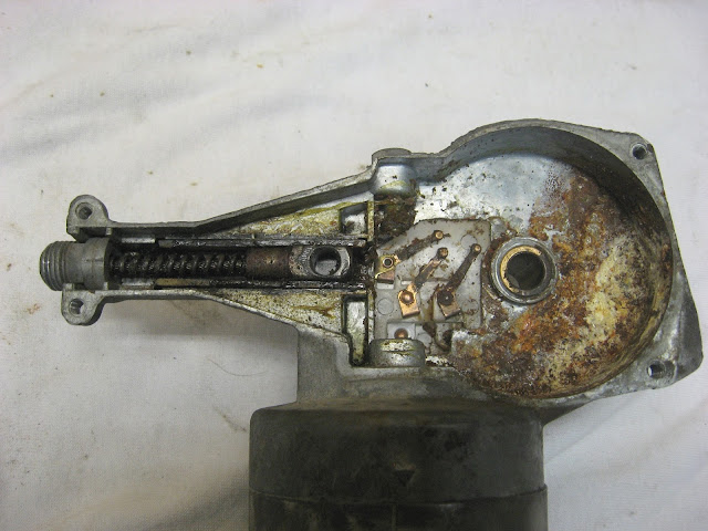
I've seen other people adapt the Mini wiper motor to the Starlet wiring loom, but to be 100% sure it wasn't going to draw too much current, I bench tested the Starlet motor (@13.2 Volts) and it was 1.88A on high speed. I tried the new Mini motor and the motor was not moving. I pulled the motor apart to find that the brush retaining plate was broken and several of the carbon brushes damaged. I had bought it (brand new) over a year ago so no warranty :( but I found a new plate and carbon brushes and fixed it.
Image

Once repaired, I tested the Mini wiper motor and the current draw was 2.2 Amps. At only 320mA more than the Starlet motor, this meant the Starlet wiring size should easily be up to the task of running the Mini motor. Using the Mini-to-Starlet wiring details here (
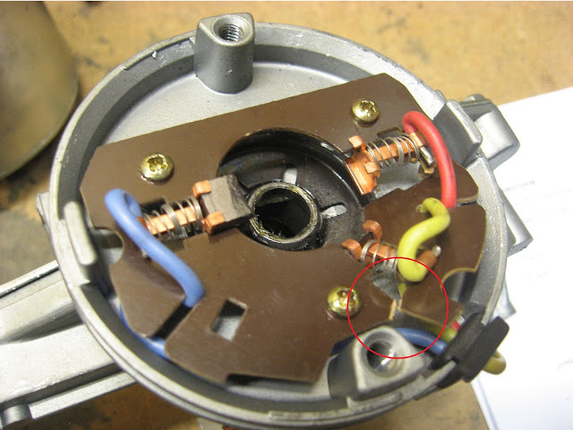
viewtopic.php?f=23&t=65707) I wired up the Mini motor and confirmed all low, high, variable intermittent & park worked via the Starlet switchgear :D

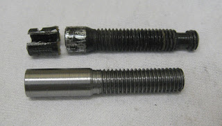
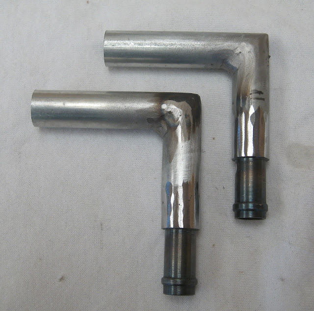
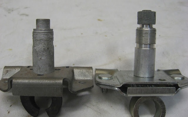
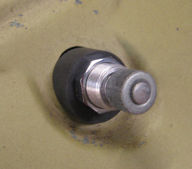
The problem with the UK-sourced wiper motor ferrule has a thread & shape that is not interchangeable with the Aussie wiper motor assembly or rack so I decided to try something a little challenging and make my own. The old Australian Mini ferrule, the ferrule for the new motor, and custom ferrule I made.
Image

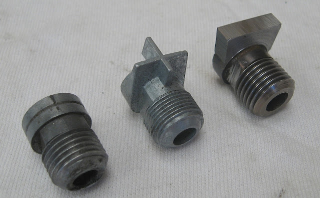
The custom ferrule fits nicely in the new motor housing with the top piece of it designed to (mostly) seal the mechanism
Image

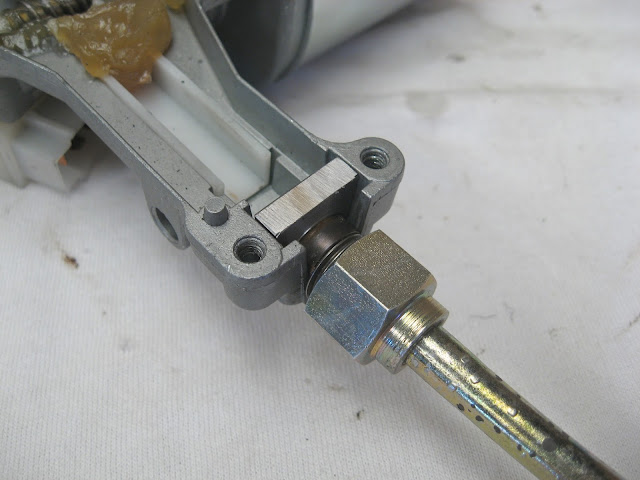
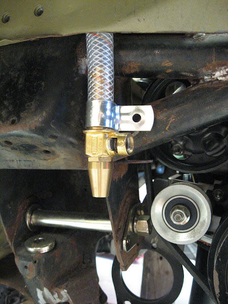
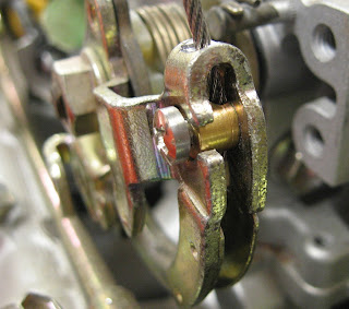
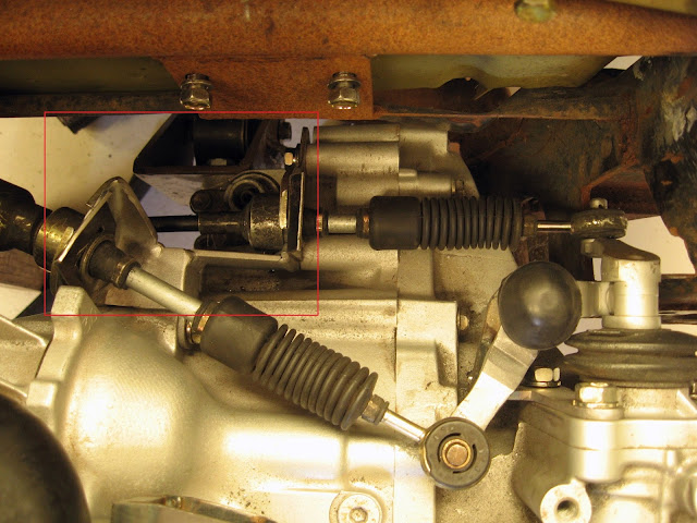
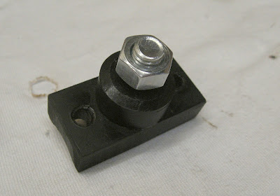
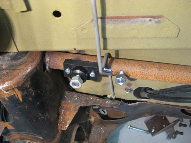
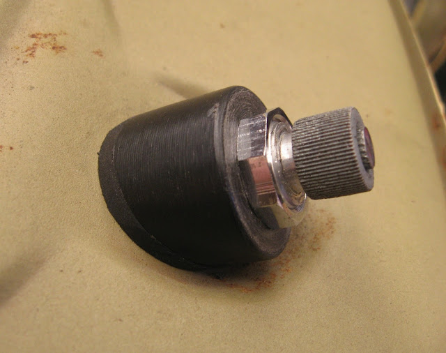
Instead of the usual 3 bolts, the Rover Mini motor uses a saddle, and rubber mounting pad between the motor and bulkhead (I assume for vibration & noise isolation) so I installed two rivnuts for the new saddle.
Image

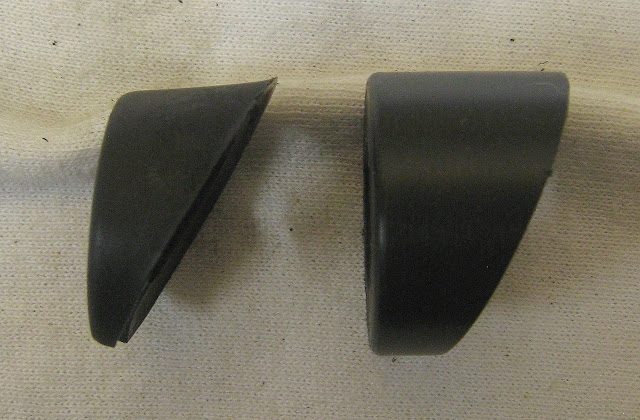
The next problem was the the rubber bushes that sit on top of the scuttle panel were also old and had gone brittle and broken and the bushes that came with the new wheelboxes were not the right shape (I assume made for the roundnose) and Clubman bushes are no longer available. This photo is of a UK bush, original (broken) Clubman bush and a UK bush I sanded down.
Image

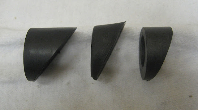
Despite the success in using my belt sander to sand down a new bush, it didn't have that the extra angle at the top of the bush (see the top of the middle bush in photo above) resulting in small 1mm gap in the panel, which would allow water to enter behind the scuttle panel.
Image

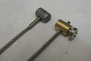
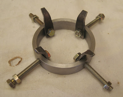
I decided to make some new ones out of black HDPE rod on the lathe where it was machined to approx 30mm OD and cut/sanded at the same angle as the original bush. The new one is also ~5mm thicker than the original bushes because the shafts of the new wheelboxes are slightly longer than the original ones. The original Australian bush and new HDPE bush :
Image

I needed a rubber washer to seal the new plastic bushes against the scuttle panel so those had to be made too - from 2mm rubber sheet.
Image

_________________
-Alan
I blame my dad for my love of minis. I think I was conceived in the back seat of one :D
I also blame my Dad for me being 6' 1" - not really the optimum height for driving a Mini.


Top
 Profile  
 
PostPosted: Tue May 22, 2018 2:53 pm 
Offline
1275cc
1275cc
User avatar

Joined: Sun Apr 29, 2012 1:19 pm
Posts: 4331
Location: Wollongong, NSW
Very neat work there. And some people wonder why it takes so long to build a custom car..

_________________
Image


Top
 Profile  
 
PostPosted: Tue May 22, 2018 3:30 pm 
Offline
998cc
998cc
User avatar

Joined: Tue Nov 13, 2007 4:17 pm
Posts: 946
Location: NOR, Perth, W.A.
timmy201 wrote:
Very neat work there. And some people wonder why it takes so long to build a custom car..

Thanks :D The most common question I get is "So when will it be finished?" where it should be "How much time has it taken?" When I start telling someone how many hundreds (or thousands?) of hours it's probably taken so far, eyes start glazing over but that is what it takes when you're doing everything yourself.

_________________
-Alan
I blame my dad for my love of minis. I think I was conceived in the back seat of one :D
I also blame my Dad for me being 6' 1" - not really the optimum height for driving a Mini.


Top
 Profile  
 
 Post subject:
PostPosted: Thu Jun 14, 2018 8:00 pm 
Offline
998cc
998cc
User avatar

Joined: Tue Nov 13, 2007 4:17 pm
Posts: 946
Location: NOR, Perth, W.A.
This build has been going for more than a few years now so I just let the Light Vehicle Modification Approval (required for any mods in Western Australia) from the Department of Transport lapse - approvals are valid for 2 years. I recently reapplied for an extension for approval and they have granted it but the one big difference between the first approval in 2009 to this one is the requirement for a collapsible steering wheel to be fitted.

I do have the factory Toyota Starlet steering column but it looks like a fair bit of work retrofitting it in the Mini. Has anyone done this before? What other options do I have?

_________________
-Alan
I blame my dad for my love of minis. I think I was conceived in the back seat of one :D
I also blame my Dad for me being 6' 1" - not really the optimum height for driving a Mini.


Top
 Profile  
 
PostPosted: Thu Jun 14, 2018 8:29 pm 
Offline
1098cc
1098cc

Joined: Wed Nov 24, 2004 10:23 am
Posts: 1488
Location: Armidale, NSW
There was a thread about collapsable columns a little while ago with a company that made collapsable columns for the mini.

_________________
---
Roads need more corners
A Deluxe(CG13DE), 2 Clubbies(998 and 1275) and 2 Morris 1100Ss


Top
 Profile  
 
PostPosted: Thu Jun 14, 2018 10:09 pm 
Offline
1098cc
1098cc

Joined: Wed Nov 24, 2004 10:23 am
Posts: 1488
Location: Armidale, NSW
Nope, I remembered it was via Facebook I saw it:
https://www.facebook.com/billetworksaus ... 6395539484

In WA as well!

_________________
---
Roads need more corners
A Deluxe(CG13DE), 2 Clubbies(998 and 1275) and 2 Morris 1100Ss


Top
 Profile  
 
PostPosted: Tue Jun 26, 2018 1:17 pm 
Offline
998cc
998cc
User avatar

Joined: Tue Nov 13, 2007 4:17 pm
Posts: 946
Location: NOR, Perth, W.A.
I've seen a few suggestions of MGB or Triumph columns in other forums and found one guy locally (Perth, WA) who used a Mk3 Ford Fiesta column for his VTEC project. By coincidence I found a guy close to my house scrapping a G102 (1989) Daihatsu Charade and it had a collapsible column. I got it for free and amazingly the spline is the same as the Mini steering rack! It will be a while until I can play around with it to see if I can use it but it seems promising as a solution.

_________________
-Alan
I blame my dad for my love of minis. I think I was conceived in the back seat of one :D
I also blame my Dad for me being 6' 1" - not really the optimum height for driving a Mini.


Top
 Profile  
 
PostPosted: Tue Jun 26, 2018 2:12 pm 
Offline
848cc
848cc
User avatar

Joined: Thu Sep 17, 2015 9:25 pm
Posts: 176
Location: Brisbane
A great story, I admire your ability to fabricate parts. My Dad was a fitter and turner, Dad-in-law a boilermaker scale maker. I used to get them to make bits and pieces for me, not so any more. Great work.

_________________
Clive G
1969 Mk II Cooper S
1970 MK II Cooper S
1963 Triumph Spitfire
1982 RX-7 Series 2


Top
 Profile  
 
Display posts from previous:  Sort by  
Post new topic Reply to topic  [ 413 posts ]  Go to page Previous  1 ... 14, 15, 16, 17, 18, 19, 20 ... 28  Next

All times are UTC + 10 hours


Who is online

Users browsing this forum: No registered users and 10 guests


You cannot post new topics in this forum
You cannot reply to topics in this forum
You cannot edit your posts in this forum
You cannot delete your posts in this forum
You cannot post attachments in this forum

Jump to:  

© 2016 Ausmini. All garage work involves equal measures of enthusiasm, ingenuity and a fair degree of irresponsibility.