Ausmini
It is currently Wed Apr 17, 2024 6:20 am

All times are UTC + 10 hours


Post new topic Reply to topic  [ 105 posts ]  Go to page Previous  1, 2, 3, 4, 5, 6, 7  Next
Author Message
PostPosted: Thu Apr 10, 2014 10:55 pm 
Offline
1275cc
1275cc
User avatar

Joined: Fri Jun 17, 2005 10:31 am
Posts: 3183
Location: Burpengary, Queensland - Home of Tricky Performance Engineering
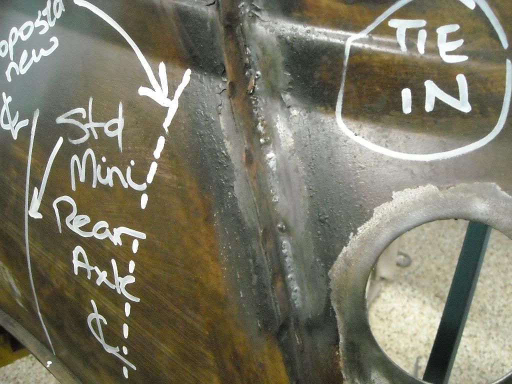
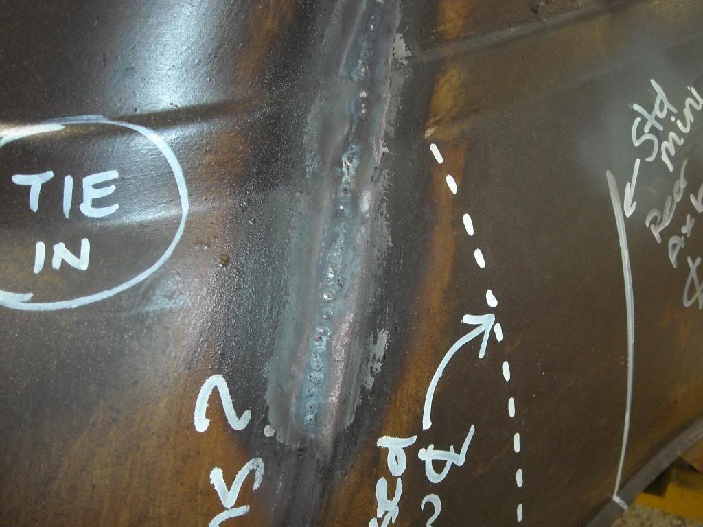
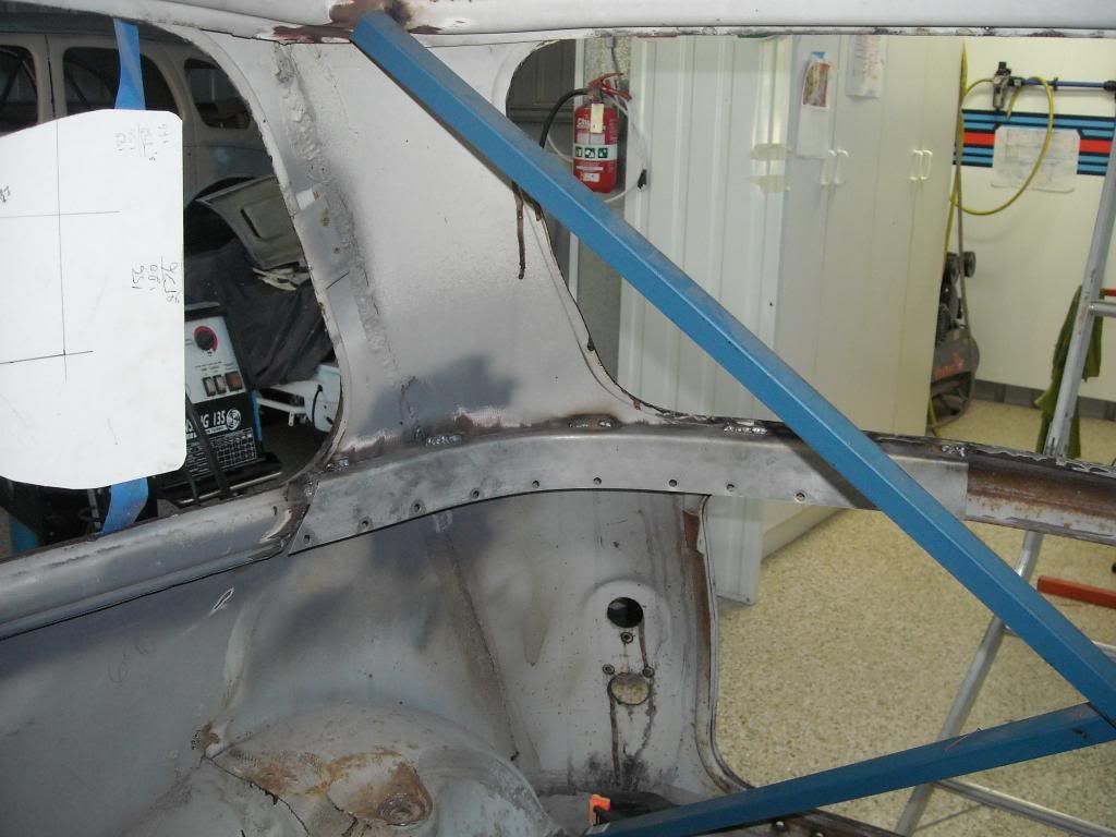
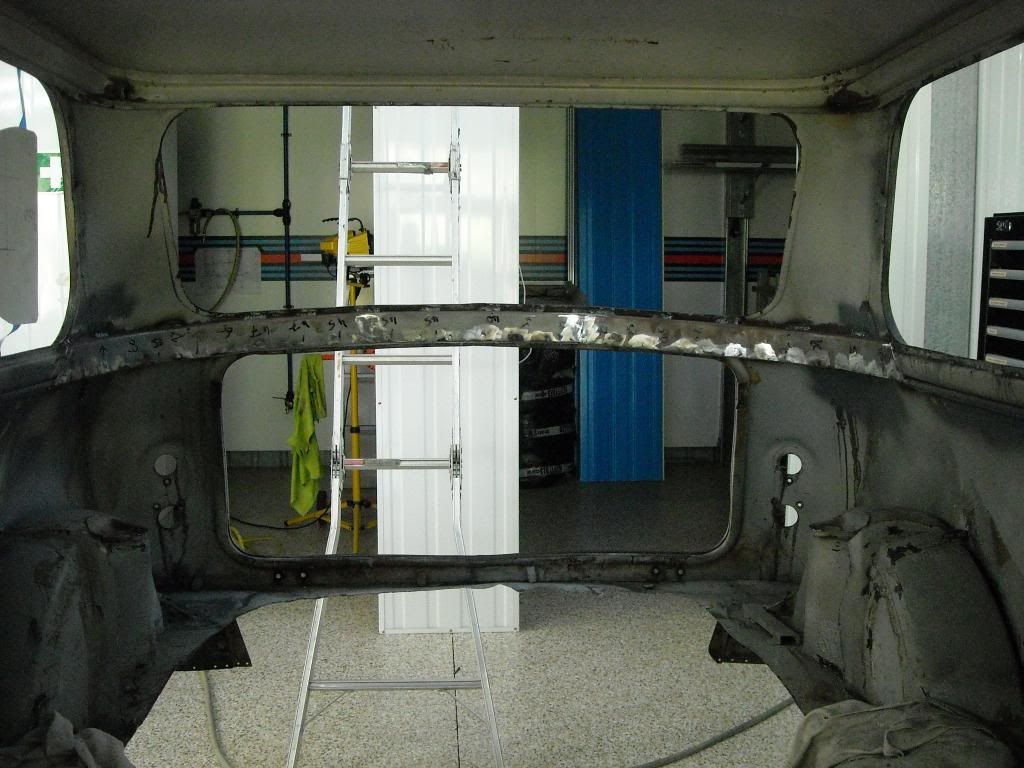
Now that the vertical bulkheads have been tied in with the beltrail, it was time to tie in the beltrails with each other, around the rear of the car, underneath the rear windscreen aperture. By adding depth to this area, it massively increases torsional stiffness, and gives us an attachment point for the engine cradle/suspension/subframe structure.

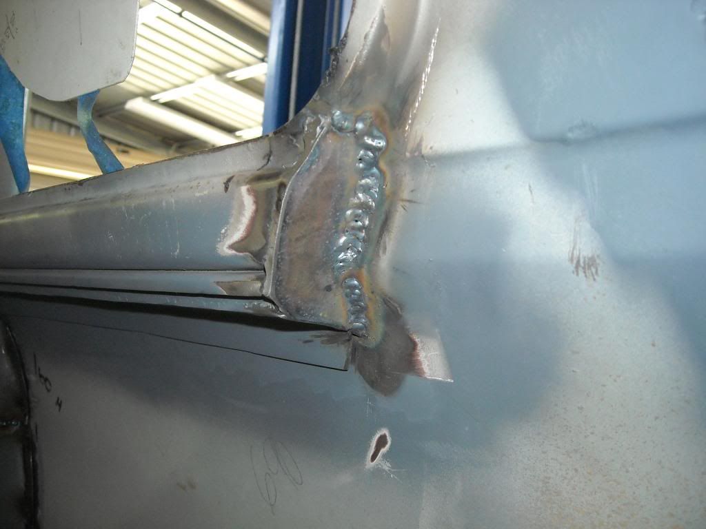
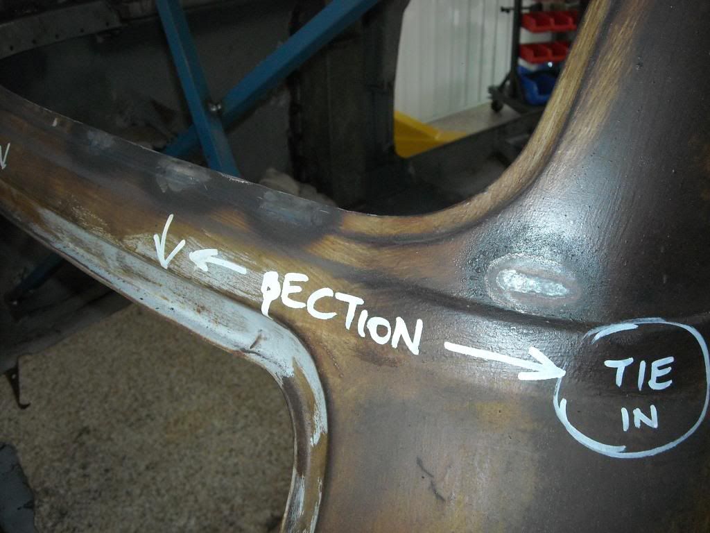
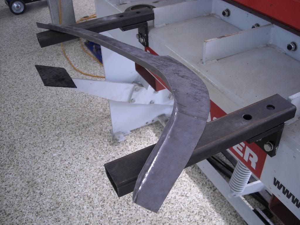
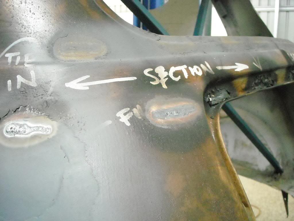
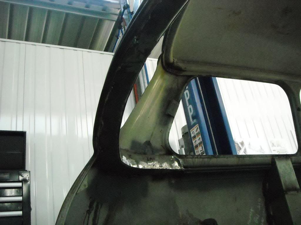
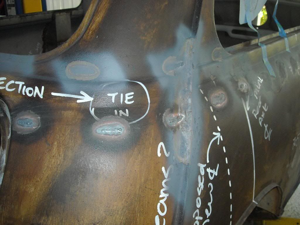
The profile of the beltrail is too complicated to reproduce and keep that profile going around the back of the car, it does not need to serve the purpose that the beltrail does, as in hold any interior trimming pieces etc, so a simple box section is easier to fabricate and install. The transition from beltrail profile to simple box profile is done through simply welding endcaps to the beltrails at an oblique angle, which will allow the box profile to be welded on to these. This is done at the point where the rear window meets the beltrail at the rearmost point.

Drivers side:
Image

Passenger side:
Image

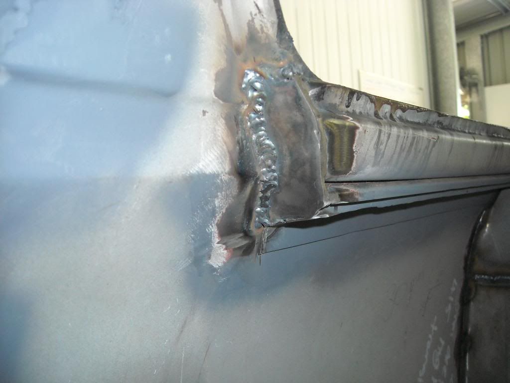
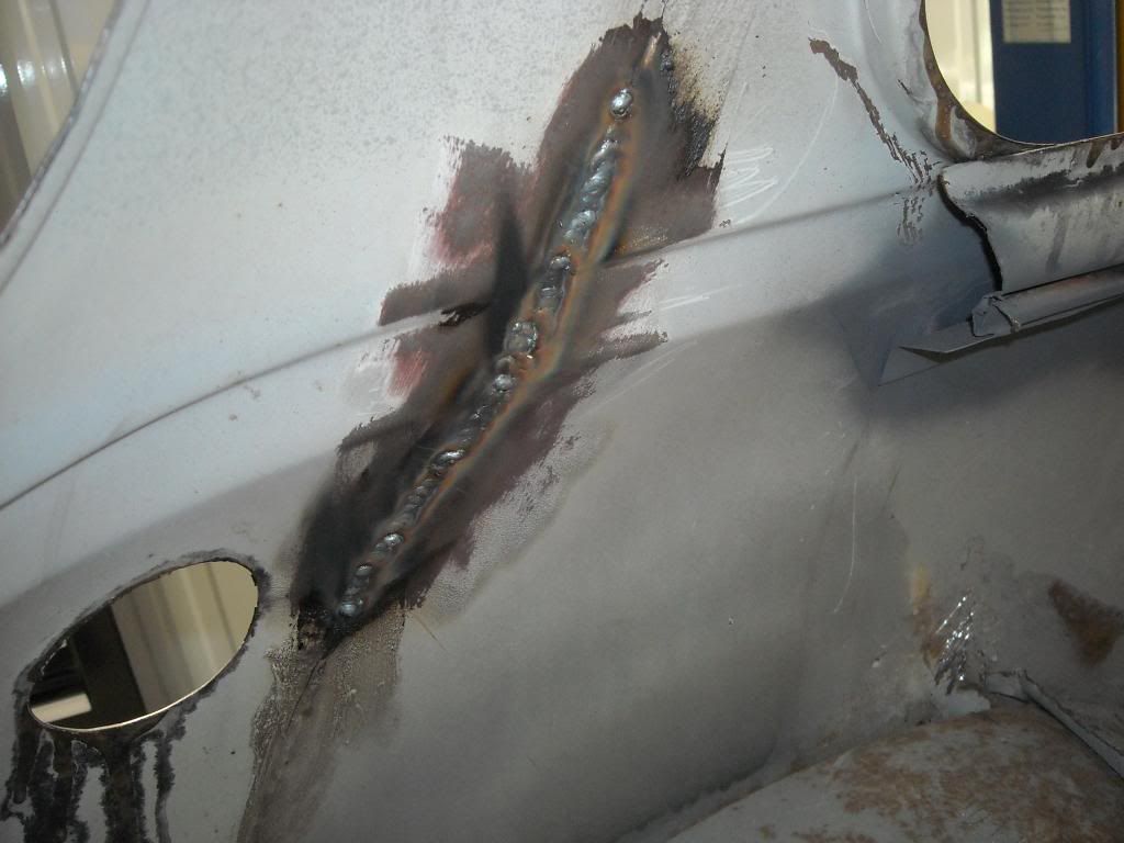
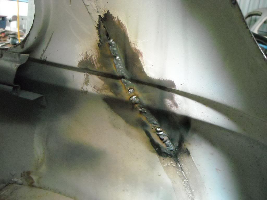
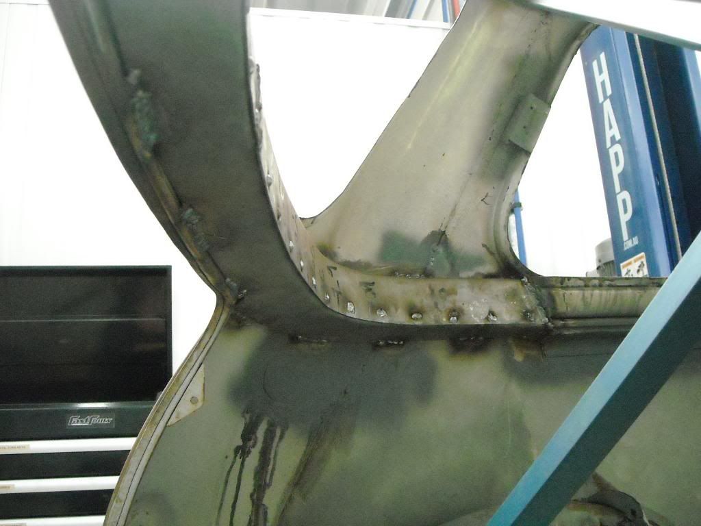
Justin has decided that the entire shell, including the roof is to be deseamed (and I thoroughly love the deseamed look of a Mini!!!). So prior to fabricating up the box-section that goes underneath the rear window, the rear seams where the box-section would cover has to be welded up. When deseaming the rear seams, I weld the seam from the backside (inside) then grind off the flanges from the outside, leaving a flush body line which is now fully one piece. You have to ensure that the weld on the inside of the seam covers the entire join, and has adequate penetration on both sides.

Inside passenger side:
Image

Outside passenger side:
Image

Inside drivers side:
Image

Outside drivers side:
Image

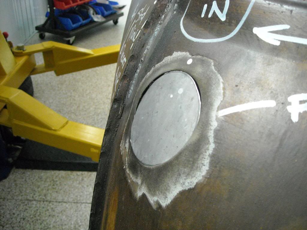
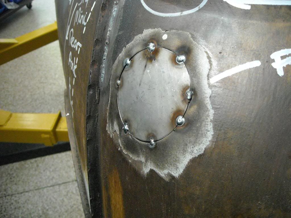
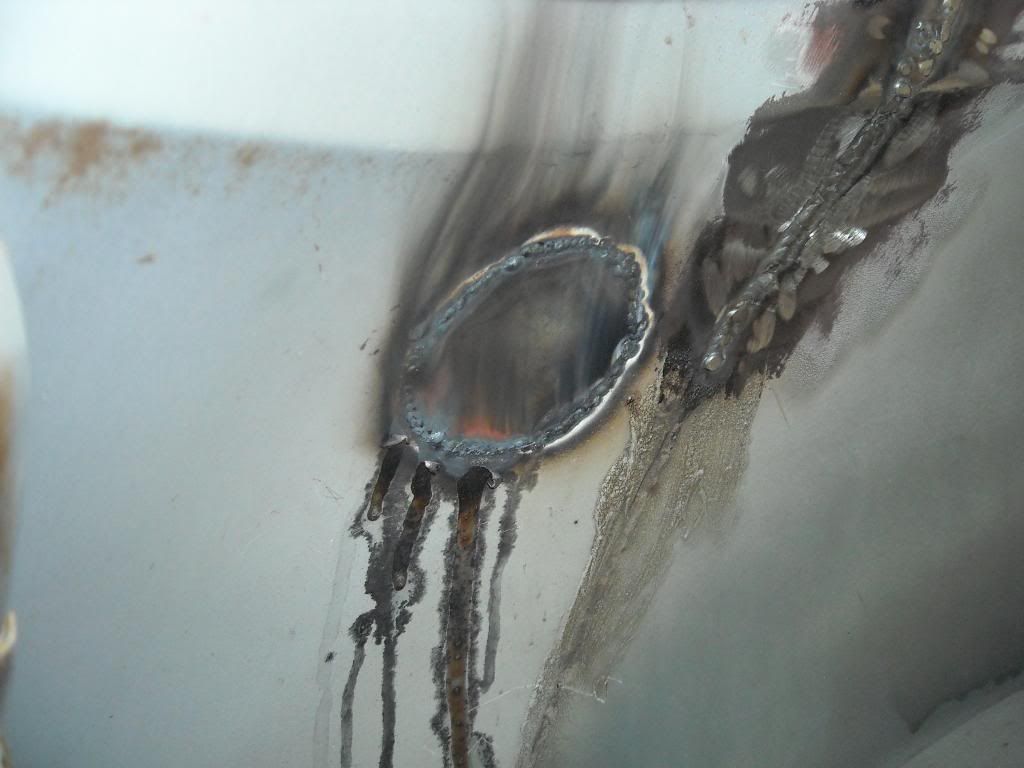
Also somehting else that needs to be done, is to fill in the fuel filler hole. As mentioned above, the fuel tank is now in the front bay, slightly offset to the passenger side to counterract driver weight. The old Mini fuel filler hole is now redundent. Its simply a case of profiling a piece of sheet on the english wheel until it is the same profile as the body (a complex curve in two planes) and then cutting it to size and then tacking it in prior to flly welding:
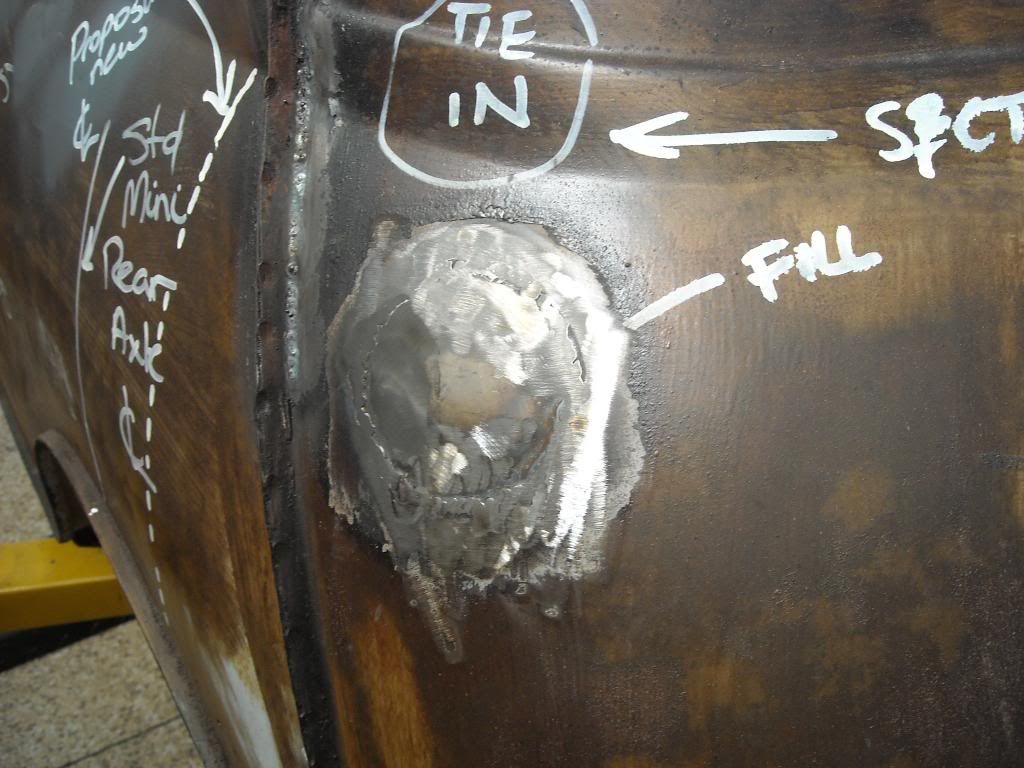
Image

Image

Image

Ground flush:
Image

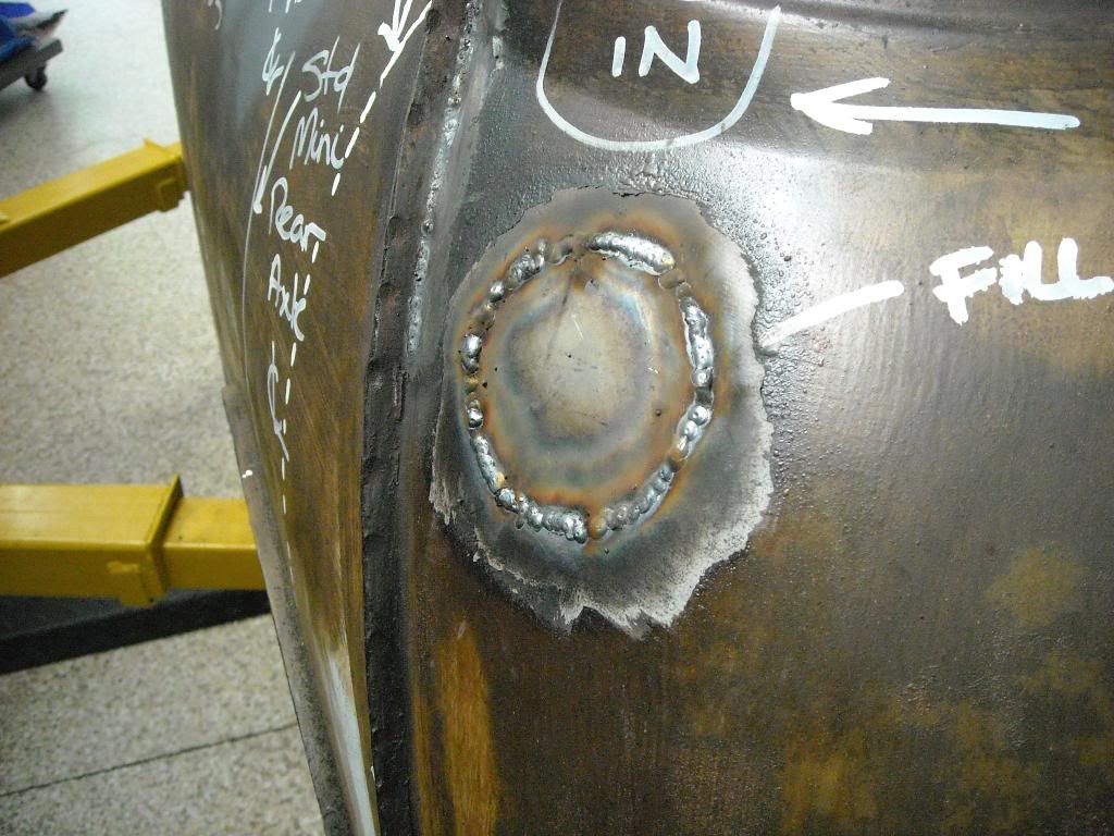
Good penetrations on the inside:
Image

We are now ready to fabricate the rear upper horizontal bulkhead. It is a complex shape, with the transition curves on the flanks leading into a larger radius curve along the rear window, and the depth and fall of the panels varying as they move from sides to back. I decided to build this complex shape in four parts - an upper and lower section and split in the middle left and right. The upper and lower pieces will overlap and be plug welded to each other through the front face, and then butt-joined to each other where they meet in the centre. The pieces will be joined onto the body by lengths of seam-weld at regular intervals.

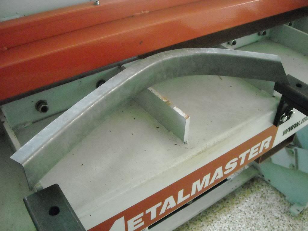
I started on the passenger side upper section, folding a piece of 1mm cold rolled steel at right angles. I then worked the lip of the profile in the shrinker/stretcher until it conformed to the profile of the body. Ths took some time to get right as any gaps to body will make it harder to weld and potentially compromise the structural integrity of the monocoque. This is what it looked like:
Image

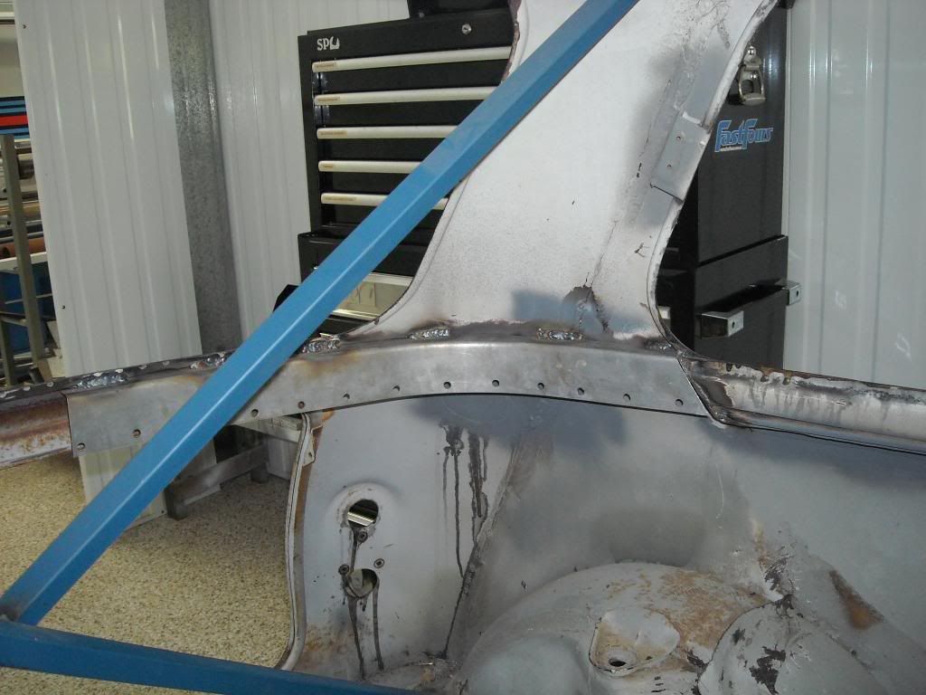
And this is how it sits against the inside of the shell, welded on with holes punched through to plug weld to the bottom section. Note the crossbracing still in place to ensure that the shell shape and profile is unaltered as we work on the rear bulkhead:
Image

And good penetrations to the outside of the shell:
Image

Drivers side:
Image

Image

The lower sections were more of the same, except upside down. One the lower sections, because of the altering depth to the body, used CAD - Cardboard Aided Design - to get the correct profile and shape, prior to cutting and bending in the panbrake. Because of the depth to body being significantly larger than on the upper pieces, the curve had to be cut out and not profiled as you would in the shrinker/stretcher. A simple lip was turned up and dreesed using the hammer and dolly method:Image

And then trimmed and welded in position, and the plug welds welded through the face, to essentially make the two pieces one:
Image

Good penetrations through to the shell:
Image

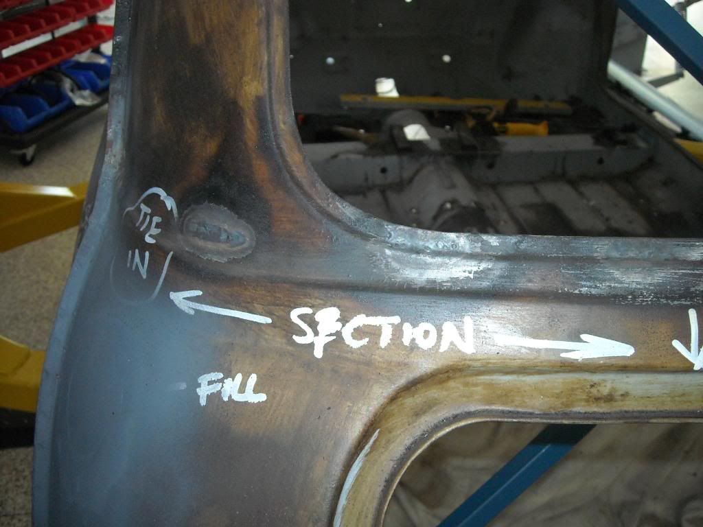
And when the drivers side was done, this is what the finished bulkhead looks like - it makes this rear section extremely strong and now the crossbracing can be removed as well. From this photo you can see how complex the shape was to imitate and get right:
Image

Plug welds ground and the transition with the beltrail dressed:
Image

Once again good penetrations to the shell:
Image

Now that this is done, this horizontal bulkhead now enhances the structural performance of the monocoque, and can be used as an attachment point for the rear subframe assembly.

Cheers,
Tricky

_________________
"Not Speeding Officer..........Qualifying"


Top
 Profile  
 
PostPosted: Fri Apr 11, 2014 6:47 am 
Offline
1098cc
1098cc
User avatar

Joined: Wed Jun 02, 2010 7:25 pm
Posts: 1335
Location: Brissy
Wow!!
Looking really nice

_________________
Tim
Dusk Blue
1964 850


Top
 Profile  
 
PostPosted: Fri Apr 11, 2014 7:28 am 
Offline
848cc
848cc

Joined: Thu Apr 26, 2007 8:16 pm
Posts: 85
Image


Top
 Profile  
 
PostPosted: Fri Apr 11, 2014 6:46 pm 
Offline
1275cc
1275cc
User avatar

Joined: Thu May 24, 2007 7:19 pm
Posts: 5370
Location: Yandina,Sunshine Coast,QLD
Did you think about double skinning/bracing the C pillar to tie the new belt rail to the roof rail? (like the B pillar is).

_________________
Respect mine and I'll respect yours.


Top
 Profile  
 
PostPosted: Fri Apr 11, 2014 9:53 pm 
Offline
1275cc
1275cc
User avatar

Joined: Fri Jun 17, 2005 10:31 am
Posts: 3183
Location: Burpengary, Queensland - Home of Tricky Performance Engineering
Kennomini wrote:
Did you think about double skinning/bracing the C pillar to tie the new belt rail to the roof rail? (like the B pillar is).


Good Question Kenno....
It wasnt required Kenno as it wasn't part of the designed load path(s)...
It would have just added extra cost and weight, both of which must be kept to an absolute minimum.

Hopes this makes sense.

Cheers,
Tricky

_________________
"Not Speeding Officer..........Qualifying"


Top
 Profile  
 
PostPosted: Sat Apr 12, 2014 9:11 pm 
Offline
848cc
848cc
User avatar

Joined: Wed Mar 14, 2007 3:50 pm
Posts: 404
Location: MORNINGTON PENINSULA
wow just awesome bro :D

Im loving this build

Cheers Hallsey


Top
 Profile  
 
PostPosted: Sun Apr 13, 2014 7:04 pm 
Offline
1275cc
1275cc
User avatar

Joined: Fri Apr 25, 2008 2:34 pm
Posts: 2002
Location: Brisbane
Love how much effort goes into making it stay a monocoque.
Would be easier to make it a spaceframe inside the shell to bolt everything to it. Just wouldn't be right though.

_________________
Simplify and add lightness


Top
 Profile  
 
PostPosted: Mon Apr 14, 2014 2:37 am 
Offline
1098cc
1098cc
User avatar

Joined: Thu Sep 30, 2004 3:12 pm
Posts: 1461
Location: Brisbane
Seems like a lot of work happening at a decent pace!

_________________
If you want more inches, stroke it
Life's a garden.... Dig It!
http://www.ausmini.com/forums/viewtopic.php?t=20746


Top
 Profile  
 
PostPosted: Mon Apr 14, 2014 9:20 pm 
Offline
1275cc
1275cc
User avatar

Joined: Fri Jun 17, 2005 10:31 am
Posts: 3183
Location: Burpengary, Queensland - Home of Tricky Performance Engineering
Thanks everyone for the very kind words and support - really appreciated!!

I am loving this build too, loving the challenge and loving the outcome!!
Its going to be f*&king epic when its done!!

Will update the build thread soon.

Cheers,
Tricky

_________________
"Not Speeding Officer..........Qualifying"


Top
 Profile  
 
PostPosted: Tue Apr 15, 2014 2:15 pm 
Offline
998cc
998cc
User avatar

Joined: Sun May 24, 2009 1:25 am
Posts: 749
Location: St George, Parramatta
Loving the build so far. Will definitely be fu(king epic!

_________________
1963 850 - laid up
1970 Morris mini K van - eating up the kms!


Top
 Profile  
 
PostPosted: Sat Apr 26, 2014 8:56 pm 
Offline
1275cc
1275cc
User avatar

Joined: Fri Jun 17, 2005 10:31 am
Posts: 3183
Location: Burpengary, Queensland - Home of Tricky Performance Engineering
I hope he lives up to his name then!!

Quick Update:

With the upper rear bulkhead done, it was time to turn my attention to the subframe attachment points at the front. At the front, to the rear of the firewall, will be two sets of mounting points - upper and lower. I decided to tackle to lower first.

The strongest part of the Mini at the rear, is the junction of the sills and vertical bulkhead where the standard rear subframes bolts up. In the design, this was always planned to be reused, and form part of the new subframe lower mounts - but greatly reinforced.

To start with, the area around the standard mounting points need to be cut away, so a smooth tie-in with the rear transverse bulkhead can be attained. This allows the design to spread load into the transverse and vertical bulkheads and back along the sills - which is the intended design path. This area included the last remnants of the old floor to the rear of the new rear transverse bulkhead, some of the sill metal, and the sheet metal leading up to the rear wheel arches. Out with the 4-inch grinder and it was gone:
Image

Which left us with a really nice transition of the floor to bulhead and also the bulkheads to sills:
Image

This just left the sill proper on both sides. This needed to be tied-in with the new rear transverse bulhead with some 1.0mm sheet. I ended up doing this at a 20-degree angle, to allow for the subframe to be removed from the car by directly undoing all the attachment points, and lowering it. The angle helps with physically getting to the fixings, and also allows for the fixings to be tightened without binding against the inner sills.

Sheet in place passenger side:
Image

Sheet in place drivers side. You can see the original Mini rear subframe mounting holes:
Image

At this point, the existing Mini rear subframe mounting holes were re-tapped to take 8mm fasteners - there will be no Imperial fasteners on this car, only Metric!

Time for some reinforcing. The inner face (the face that faces inwards) will be the new attachment point for the subframe, as well as wrapping around the corner to pick up the old subframe mounting points (now 2 x 8mm per side). To do this, we grabbed some 3mm plate and cut it to size. Because captive nuts will be welded to the inside of this plate, some 20mm holes were drilled into the sheet face with a 20mm holesaw to allow for the nut and weld to project through into the cavity.
Holes made in the 1.0mm sheet to allow for the captive nuts to protrude through:
Image

3mm plates with te captive nuts welded on:
Image

Bringing the two together produces an extremely strong mounting point for the subframe - far stronger than what was originally there, but then again it has to be to cater for the new loads. The simple geometric shape, by welding the 1.0mm plate back to the transverse bukhead at a 20-degree angle, has provided depth to the structure which in turn gives it added strength, and reduces any liklihood of deformation due to torsional, compressive or tension loads imparted by the subframe.

The passenger side mounting point now reinforced:
Image

Drivers side:
Image

So, on each side, at the bottom, there is 2 x 12mm and 2 x 8mm fixings holding the subframe in place. Combine this with the upper mounting points, and the subframe will be very securely attached to the car.

More soon.

Cheers,
Tricky

_________________
"Not Speeding Officer..........Qualifying"


Top
 Profile  
 
PostPosted: Sun Apr 27, 2014 7:00 pm 
Offline
848cc
848cc
User avatar

Joined: Wed Mar 14, 2007 3:50 pm
Posts: 404
Location: MORNINGTON PENINSULA
loving it :D

Cheers Hallsey


Top
 Profile  
 
PostPosted: Sun Apr 27, 2014 9:44 pm 
Offline
1275cc
1275cc
User avatar

Joined: Fri Jun 17, 2005 10:31 am
Posts: 3183
Location: Burpengary, Queensland - Home of Tricky Performance Engineering
Me too bro!!

_________________
"Not Speeding Officer..........Qualifying"


Top
 Profile  
 
PostPosted: Sun May 04, 2014 9:30 am 
Offline
998cc
998cc
User avatar

Joined: Mon Oct 25, 2004 7:17 pm
Posts: 1121
Location: Bundaberg, QLD
OMG, you are going to out do yourself Tricky

_________________
Baracade
Relationships! The only time you get to sleep with the enemy!
1972 US Export Moke in Bundaberg QLD


Top
 Profile  
 
PostPosted: Mon May 05, 2014 4:11 pm 
Offline
1275cc
1275cc
User avatar

Joined: Fri Jun 17, 2005 10:31 am
Posts: 3183
Location: Burpengary, Queensland - Home of Tricky Performance Engineering
Hey Dean,

Welcome back!! Yes, it should be a fine weapon when its done - maybe fine enough to rival BigBad!! :shock:

What are you up to with your Mini??

Cheers,
Tricky

_________________
"Not Speeding Officer..........Qualifying"


Top
 Profile  
 
Display posts from previous:  Sort by  
Post new topic Reply to topic  [ 105 posts ]  Go to page Previous  1, 2, 3, 4, 5, 6, 7  Next

All times are UTC + 10 hours


Who is online

Users browsing this forum: No registered users and 9 guests


You cannot post new topics in this forum
You cannot reply to topics in this forum
You cannot edit your posts in this forum
You cannot delete your posts in this forum
You cannot post attachments in this forum

Jump to:  

© 2016 Ausmini. All garage work involves equal measures of enthusiasm, ingenuity and a fair degree of irresponsibility.