ausmini
https://www.ausmini.com/forums/

Fuel level sender - resistance ranges
https://www.ausmini.com/forums/viewtopic.php?f=23&t=99674
Page 1 of 1

Author:  Mearcat [ Tue Feb 11, 2020 11:25 am ]
Post subject:  Fuel level sender - resistance ranges

For anyone who has done an engine swap and used the Mini fuel tank, how have you dealt with the fact that the Mini level sender range is ~30-290 Ohms, and most modern cars are something like 5-105 Ohms. How have did you get the Honda/Toyota/Daihatsu etc fuel level gauge to calibrate/work with the Mini sender?

Author:  Dickywhizz75 [ Tue Feb 11, 2020 2:49 pm ]
Post subject:  Re: Fuel level sender - resistance ranges

Alan, I have a PCB mounted on my fuel sender which has resistors on it that could be changed to any values you wanted! I chose to make a PCB when the arm had worn through the wires in the sender. It isn't perfectly analog but does have 23 steps from full to empty! :D

Author:  timmy201 [ Tue Feb 11, 2020 2:56 pm ]
Post subject:  Re: Fuel level sender - resistance ranges

You can get converter boxes like this
https://www.enginemaster.com.au/fuel-link

I also vaguely remember Howard’s instruments were able to adjust the sender to match any gauge (and probably vice versa)

Author:  Timbo [ Wed Feb 12, 2020 4:30 pm ]
Post subject:  Re: Fuel level sender - resistance ranges

These guys are familiar with Minis and do a converter https://www.spiyda.com/fuel-gauge-wizard-mk3.html

Tim

Author:  Harley [ Wed Feb 12, 2020 5:21 pm ]
Post subject:  Re: Fuel level sender - resistance ranges

I've done two methods with success:
1. Spiyda converter as noted above, and
2. Remove mini sender, and replace with an aftermarket one that is a standard 0-90ohms. This method really only works on injected tanks though as you need to use the pump access hole in the top to work out what arm length you need to setup in the tank.

Author:  Mearcat [ Mon Dec 28, 2020 8:54 pm ]
Post subject:  Re: Fuel level sender - resistance ranges

For the purposes of freedom of information, here's an extract from my build thread. Motivated with info from Dickywhizz75 above :

With the Mini fuel level sender providing a resistance range of 30 Ohms (full) and 290 Ohms (empty) it was nowhere near the same as the Toyota instrument that used a range of 4-114 Ohms. I considered this idea of replacing the rheostat in the fuel level sender with a custom circuit board.

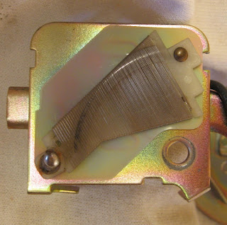
Making the custom fuel sender circuit board was a relatively easy process - pull apart the factory sender rheostat, make some measurements
Image

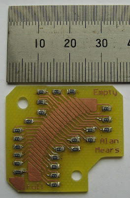
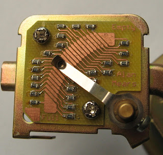
Using a free PCB maker program called Circuitmaker, I copied the layout of the factory rheostat. The small custom board (37mm x 33mm) was designed to have twenty four 4.7 Ohm SMD resistors wired in series to get a ~5-113Ohm resistance range. It was a great way to solve the problem of mismatching ranges between the Mini and Toyota Starlet. I had a bare PCB milled and the board and realised that I'd screwed up the sweep angles so had to do it over again! Once the design was corrected and new boards milled, it was then screwed back onto the sender assembly
Image

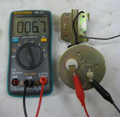
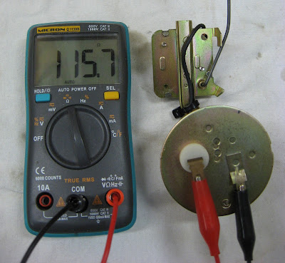
Soldering the tiny 0805 size SMD resistors (2.0mm x 1.3mm each) to the circuit board was fiddly but once done, the board was screwed onto the sender assembly.
Image
Image
Image

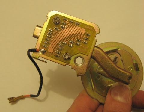
Testing showed that the range was pretty dang close to the Toyota instrument. I actually made two sender PCBs so I've got a spare.
Image
Image

Page 1 of 1 All times are UTC + 10 hours
Powered by phpBB® Forum Software © phpBB Group
http://www.phpbb.com/