Ausmini
It is currently Sat Apr 27, 2024 8:22 pm

All times are UTC + 10 hours


Post new topic Reply to topic  [ 9 posts ] 
Author Message
PostPosted: Thu Aug 03, 2023 9:05 am 
Offline
848cc
848cc

Joined: Sat Dec 13, 2014 8:55 am
Posts: 49
Location: France
Hi everyone,
I don't know if this is the right place to talk about this project, but feel free to move it if you need to.

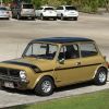
For those of you who don't know me, let me introduce myself quickly. I've been working on minis since I was twelve thirteen years old, and I've learnt a lot with these cars (carburetion, ignition, mechanical design, etc.).

Now, as an industrial engineering student, I wanted a project that was a bit more substantial and complete than what I'd been able to do up until now.

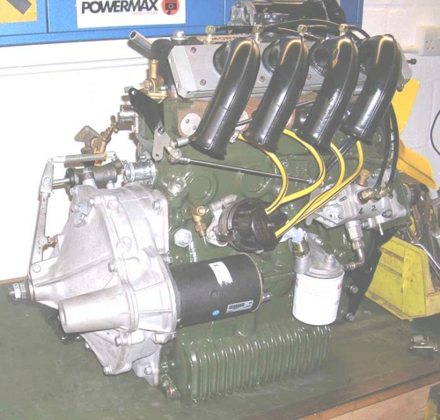
As some of you know, I have been working for a while time on the modelling of 8 port cylinder heads.

(as Trog was able to do with his cylinder head, thanks for sharing!)

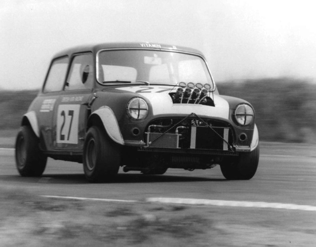
The obejctive would be to revive the group two cylinder head.
Image

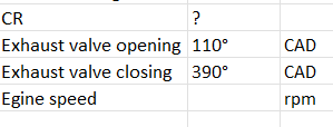
So the first step was to read the documentation for this competition.
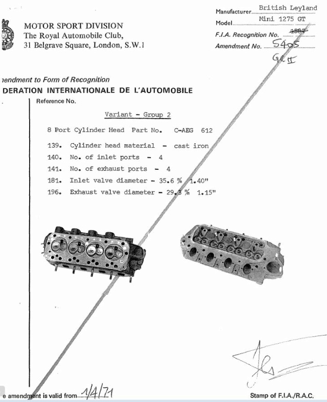
Image
Image
(source mk1 forum)

and finally, the regulations only require a few elements to be able to respond to this group's cylinder heads, which is good news!

After a year's research, I was able to start the work of modelling, understanding and analysing, which will enable this model to be competitive.

This work required a lot of time, a number of simulations, and also the development of a number of 3D printed prototypes.

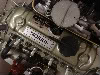
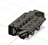
The first of many steps was to determine the location of the important components of the cylinder head, i.e. the studs, the rocker arm passages, the coolant passages and the oil passages.
Image

Once the elements had been designed, I printed them out to check the accuracy of the design.
Image
Image


Next step, the shape of the intake and exhaust ducts and the combustion chamber had to be determined.
Although as an engineering student I have access to interesting resources, but this part was extremely time-consuming.

The following images are not from the latest simalutions or designs (to protect my work I hope you'll understand). .
But they are useful for illustrating the post.
As you can see, I carried out a number of CFD simulations in order to optimise the flow of the cylinder head.
This was useful, because it's 'quite complicated' :) to predict how a fluid will react depending on its velocity and the shape of the duct through which it flows.

The influence of the shape of the intake manifold on the flow is important, and simulations make it easier to interpret the results.
Image
Image
Image
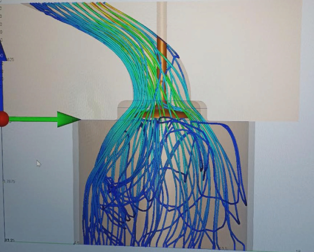
(non-contractual photo)

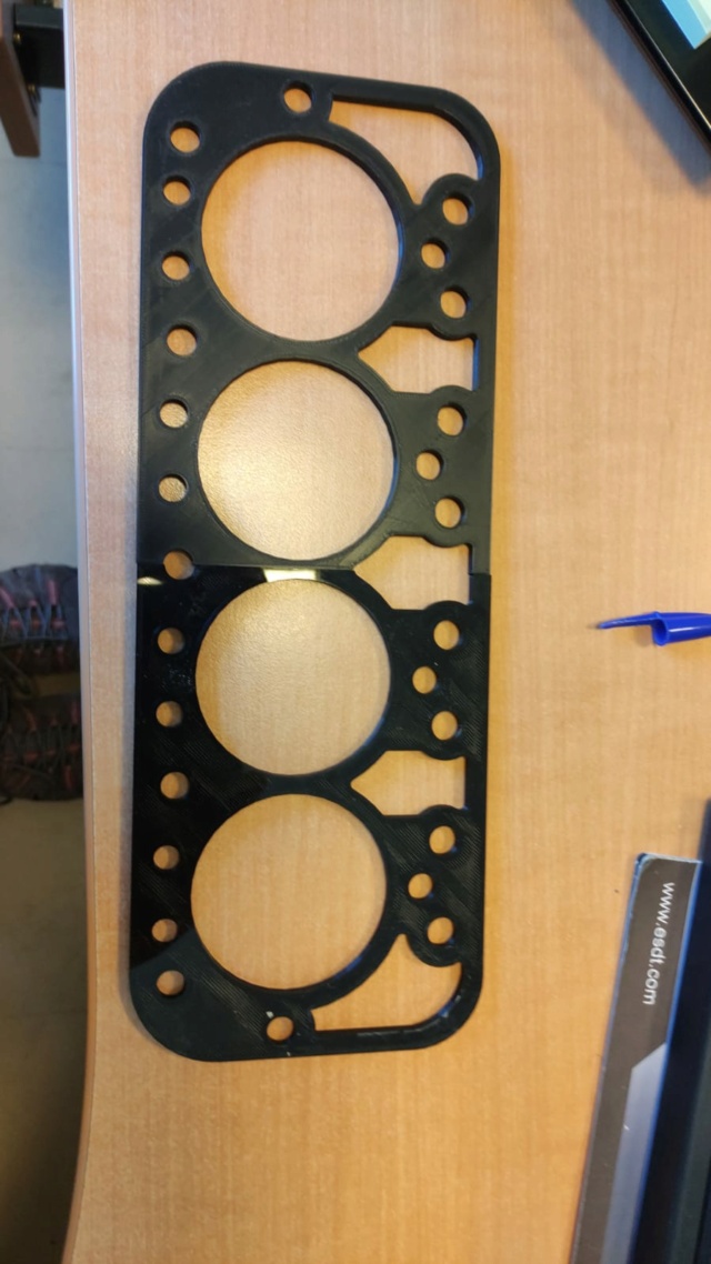
finally, after a few (many) hours, I managed to get a complete design
Image

I've printed the whole thing out to check it.
but as it's a big piece, i had to do it in four parts, you can see the joins and the lack of detail, effectively it's a lightened version because concerning the time it's the equivalent of more than 4 days of printing 24/24.

Image
Image
Image

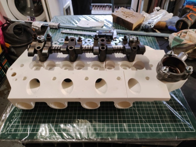
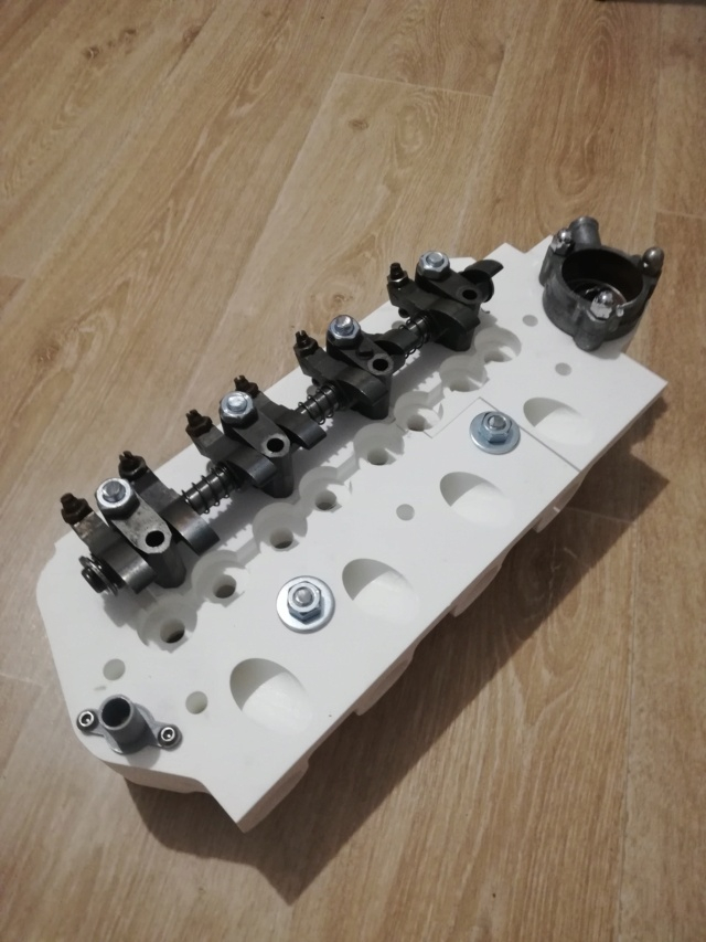
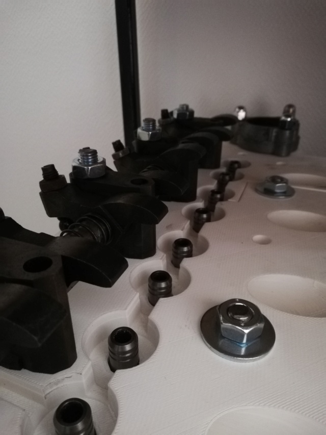
threaded rods are only used to hold 3d printed parts in place :lol: .

I won't be posting any photos of the chambers, final ducts or intake manifold for the time being. However, I hope you'll be interested in the project, and I'll be happy to talk about it.

Cheers


Top
 Profile  
 
PostPosted: Thu Aug 03, 2023 11:55 am 
Offline
1098cc
1098cc

Joined: Wed Sep 30, 2015 9:38 am
Posts: 1504
Location: Brandy Hill, NSW
What a wonderful job you have done, congrats.


Top
 Profile  
 
PostPosted: Thu Aug 03, 2023 1:07 pm 
Offline
998cc
998cc

Joined: Sun Nov 06, 2005 5:41 pm
Posts: 845
Location: Adelaide
Greet project, looks like a lot of work to date, and a long way to go for the final cast iron product. Keep us posted!


Top
 Profile  
 
PostPosted: Thu Aug 03, 2023 1:25 pm 
Offline
SooperDooperMiniCooper ExpertEngineering
User avatar

Joined: Fri Apr 29, 2005 9:46 am
Posts: 18854
Location: Under the bonnet son!
Wonderful work! Certainly, has to be enough for a 4th year Ind. Eng. design Thesis at as minimum!

Can your modelling indicate performance at part-throttle or transient load response as well? I'm really interested in the modelling, it's a brave new world in design.

_________________
SooperDooperMiniCooperExpertEngineering

All garage work involves equal measures of enthusiasm, ingenuity and a fair degree of irresponsibility.


Top
 Profile  
 
PostPosted: Thu Aug 03, 2023 8:44 pm 
Offline
848cc
848cc

Joined: Sat Dec 13, 2014 8:55 am
Posts: 49
Location: France
thank guys

In fact, we can simulate a complete engine cycle. But this requires a lot of resources, with moving parts (lift, duration, speed, etc.) and the fuel mixture. So it's simpler to run several CFD simulations with boundary conditions.

CFD analysis of flow in a cylinder head is I think one of the most difficult, because there are so many time-dependent variables (not like a simple plumbing valve, for example).
But they do enable us to understand the displacement behavior of a fluid (I don't know if I can say it like that).


Top
 Profile  
 
PostPosted: Mon Aug 21, 2023 4:10 am 
Offline
848cc
848cc

Joined: Sat Dec 13, 2014 8:55 am
Posts: 49
Location: France
Good evening everyone,

With the aim of improving our mini engines I had a few questions.
I'm going to do a dynamic CFD analysis of the cylinder head, but before I start I had a few questions.
I'm not going to do it 10 times because the calculation times are quite long.

In order to be as accurate and close to reality as possible, I want to get closer to a " realistic " configuration.

1# I have doubts about the CR to apply, a CR that is not just theoretical (ideal), I was thinking of 10.3 is a good aim ?

2# Similarly for the aac what should I simulate, to keep things simple I have in mind a range of aac Sw10 or Sw23.
However, I don't have the Sw23 timing and I'm not sure about the Sw10 timing.

3# Same for the rotation speed,

Image


the table is with Sw10 timing

If some have already done this kind of simulation, advice is welcome.


Top
 Profile  
 
PostPosted: Mon Aug 21, 2023 1:42 pm 
Offline
848cc
848cc
User avatar

Joined: Mon Sep 26, 2016 11:27 am
Posts: 356
Location: Mangilao, Guam
Wow what a nice project

_________________
1973 Clubman GT - YG2S8 1637


Top
 Profile  
 
PostPosted: Mon Sep 04, 2023 5:41 pm 
Offline
998cc
998cc
User avatar

Joined: Sun May 24, 2009 1:25 am
Posts: 749
Location: St George, Parramatta
That’s incredible work Baptiste! I can’t help answer your questions, but hopefully you can find the answers through this or another forum.

Keep up the great work!

_________________
1963 850 - laid up
1970 Morris mini K van - eating up the kms!


Top
 Profile  
 
PostPosted: Thu Oct 05, 2023 7:19 pm 
Offline
848cc
848cc

Joined: Fri Oct 06, 2017 6:39 pm
Posts: 191
Location: Perth, WA
baptiste wrote:
Good evening everyone,
If some have already done this kind of simulation, advice is welcome.


I haven't... this guy might have:
https://aseriesmodifications.wordpress.com/


Top
 Profile  
 
Display posts from previous:  Sort by  
Post new topic Reply to topic  [ 9 posts ] 

All times are UTC + 10 hours


Who is online

Users browsing this forum: No registered users and 61 guests


You cannot post new topics in this forum
You cannot reply to topics in this forum
You cannot edit your posts in this forum
You cannot delete your posts in this forum
You cannot post attachments in this forum

Jump to:  

© 2016 Ausmini. All garage work involves equal measures of enthusiasm, ingenuity and a fair degree of irresponsibility.