Thanks for the kind words gents and I appreciate the patience of everyone who is helping me out along the way. Anyways - here's the latest.
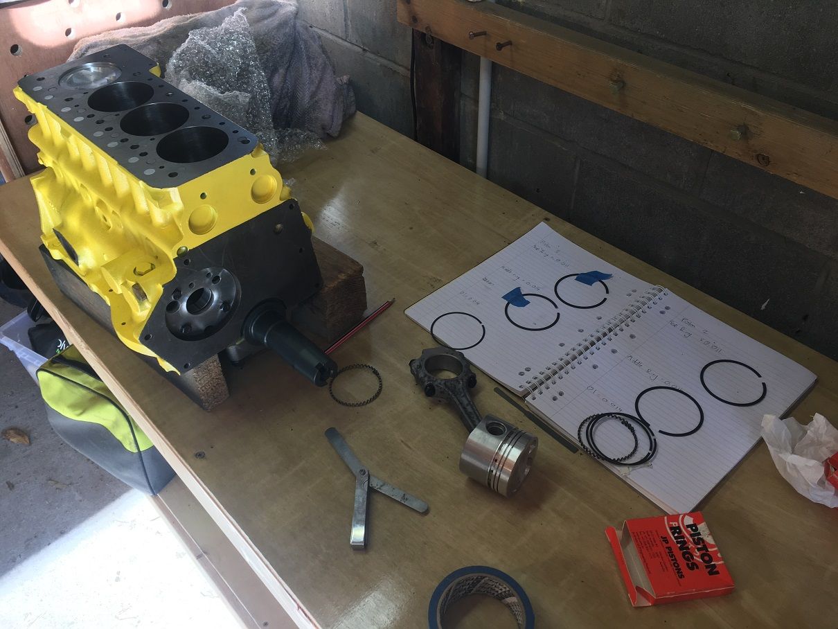
I revisited measuring the combustion volume and got the following
-13cc for the piston with fly cuts
-17cc for the cylinder head chamber
assuming ~2cc for the head gasket works out for a compression ratio of about 10.8. Cool - or should I go higher?
Piston rings gapped. 0.011" for the top ring and 0.014" for the second.
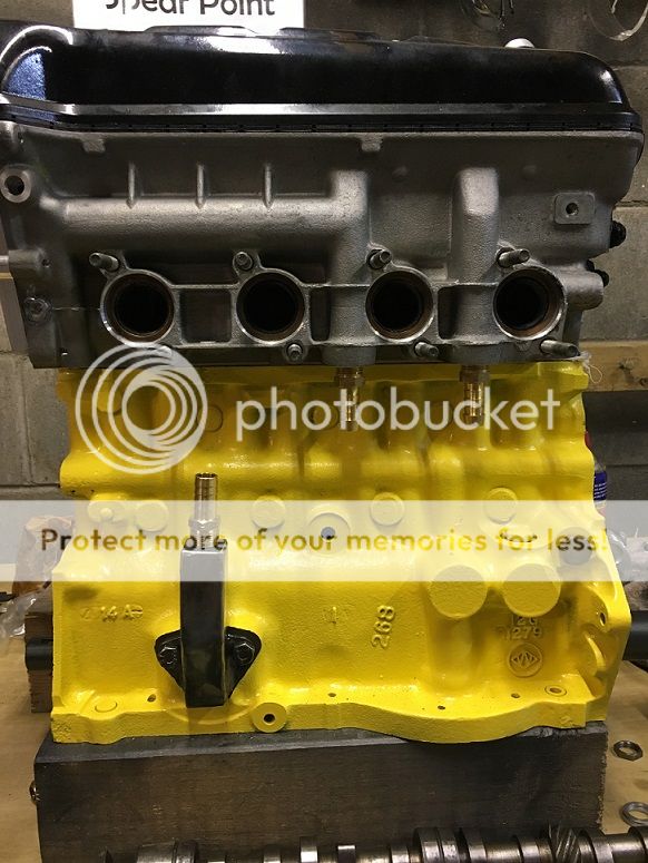
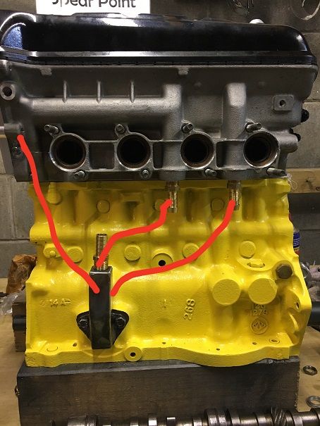
I've decided to use an external oil feed line that Matt is currently making up for me that feeds up into the back of the head - simple. The oil return isn't particularly difficult but has been consuming my time lately. I've seen on Steve's build that two barbs were tapped into the block just below the the head returns. I like this setup because it's simple but am not interested in drilling into the block and am starting to think about how difficult it may be to try and change a hose/pipe in that location. Anyway, here is what I've played with so far.
A pretty rudimentary setup that I mocked up with some RHS and a fuel pump blanking plate. The first prototype was pretty ugly but you get the idea.
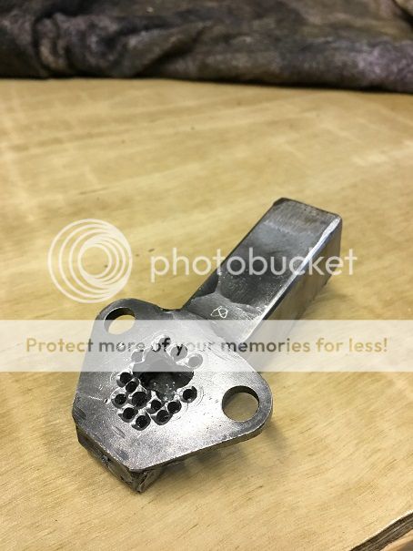
Slightly refining that prototype came this,
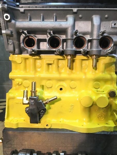
The final design is this one
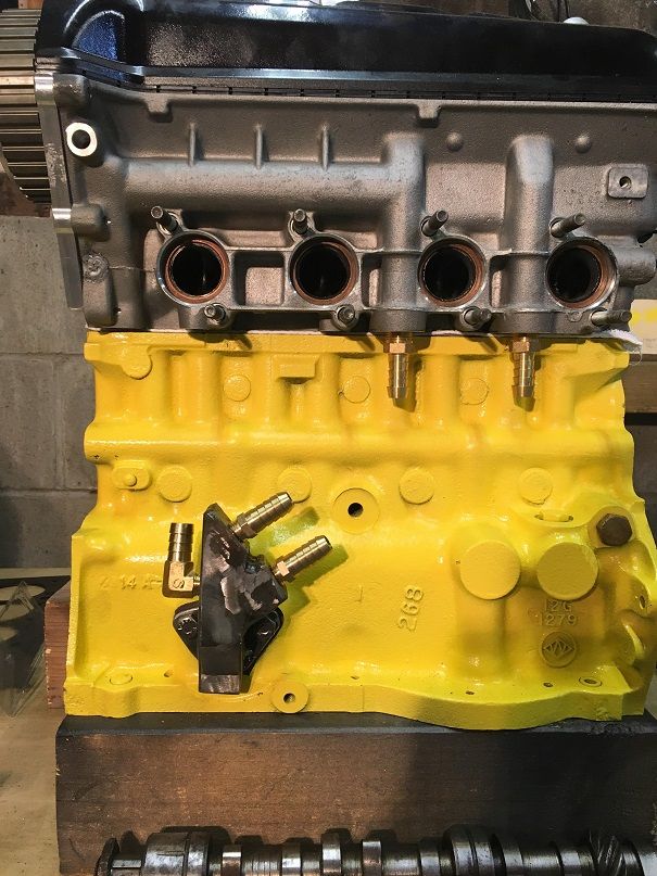
It's not perfect but I'm confident it will do the trick of draining the oil that is fed through the single feed line down into the crank case. The drain into the block will look nicer than a bunch of randomly drilled holes like the prototype was I assure you!
I don't think crank case pressure is going to be an issue as I will have the standard crank case breather on the flywheel housing and will add another one somewhere else as well. This should be able to handle the volume of oil flow noting that there is only a single feed line to the head.
Matt I want to see your go to solution for oil drains!

Cheers,
joe