Chapter 3 - contd.
With both spars in place, its time to tie them into the front eyelets. On the drivers side, this involved cutting two 6mm steel plates of dissimilar shape to allow for the 'seam' of the bodywork where the front eyelet joins the body work. The spar was then obliquely slashed to join up with this plate. Also, it was at this time that the inner guard had to be cut to accomodate the new subframe.
Pic of the subframe inside the bay during a test fit. the fit was very tight, but all holes lined up. Notice that I cut out more bodywork than I needed to (bugger!). This would be reinstated later on.
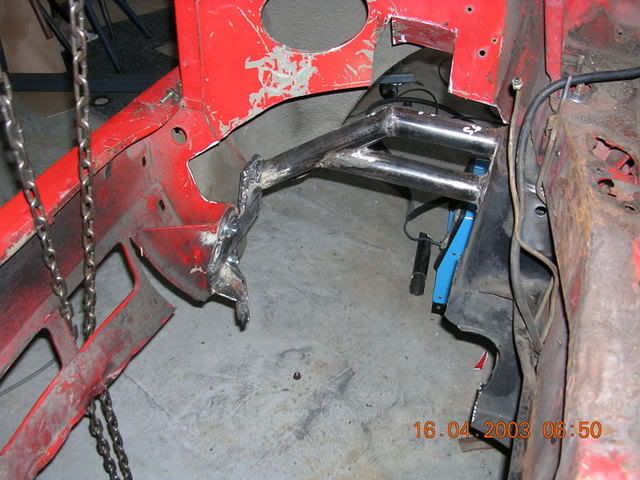
On the passenger side, the spar was redirected along the inner guard, and then turned down at 90 degress to emerge directly on top of the eyelet. The backside was cut out of the pipe by 6mm (thickness of the plate) to join onto the mounting plate that held the eylet and which mounted to the body:
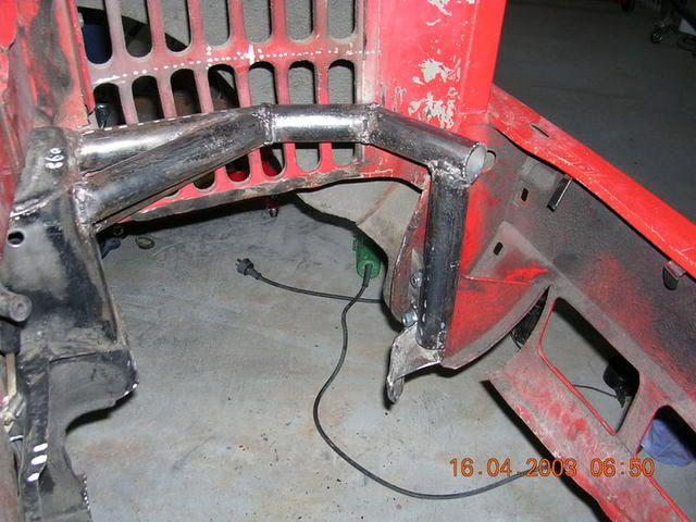
In the picture above, notice the space in front of the spar for the radiator. Also the space above the spar (where the original Mini radiator once lived) will now become the space for the cold-air box (it is mandatory in QLD that you cannot run an exposed air-cleaner or filter).
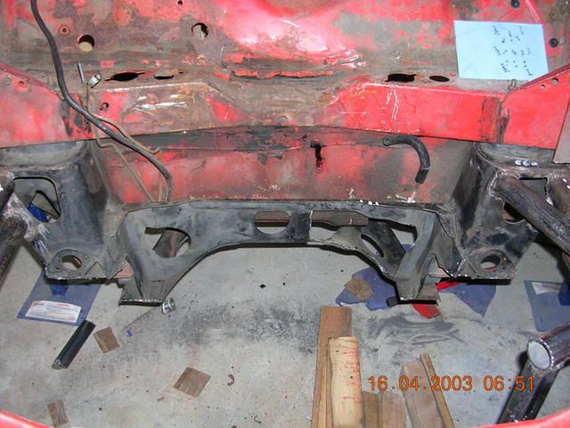
This is what the subframe looked like at the rear:
Now that the subframe was sitting in the engine bay nice and neat as you please, it was time to bring the engine in and fabricate the mounts. In the Starlet, the engine comes out from underneath. But I wanted the engine to come out from the top as well as come out from the bottom (this being one of the design criteria which influenced the overall design). To this end, the engine mounts had to cater for this design idea.
Once the engine and subframe was in the car, it was time to locate the engine precisely and take some measurements to allow the mounts to be fabricated.
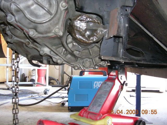
Engine supported from underneath:
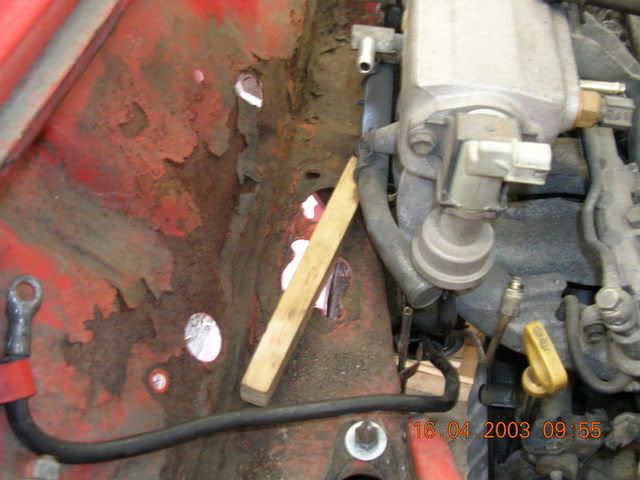
And pieces of wood used to gauge and enforce clearances:
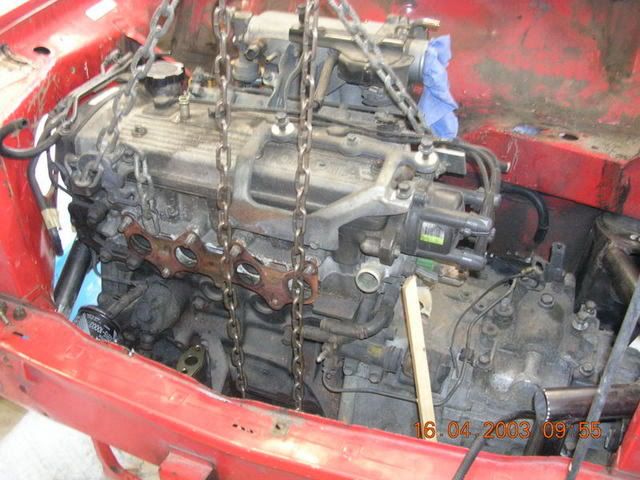
A bullet level was used on the plenum to ensure the motor was dead level. Also, after marking two identical marks on either front guard, a straight edge lined up with the exhaust manifold face was used to ensure the motor remained square:
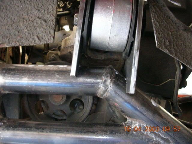
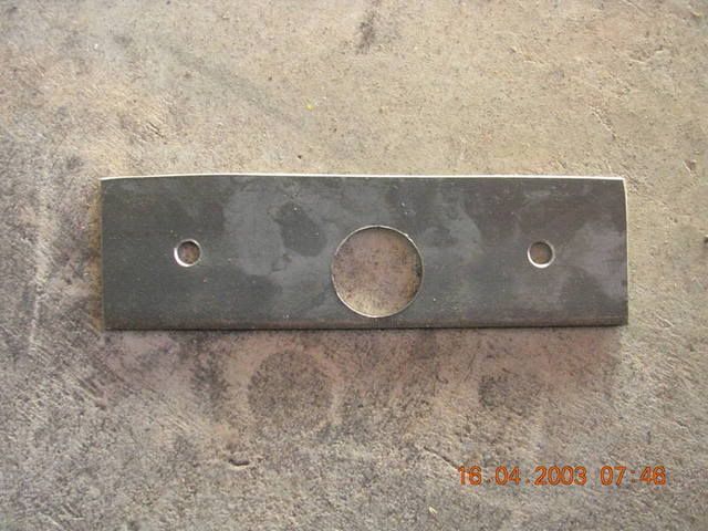
I started with the drivers side mount first. This was the easiest one. It was also the most crucial in that getting this one right would ensure that the motor was in position from left to right, and front to back. Firstly I took some measurements, and then fabricated the mount (the mount just being two upright leaves either side of the mount). I took the liberty of making either side out of one piece of steel, then cutting it across the middle. The hole (or actually half a hole when its disected) allows the mount to follow the contour of the round bar of the spar:
Then the mount was bolted into place, and after checking it for accuracy, was tack welded on. I checked the clearences and alignment again - a perfect fit. Time to weld!
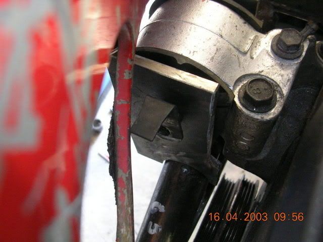
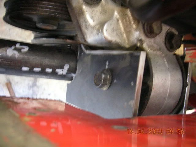
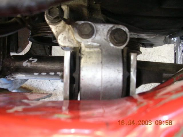
No - dont adjust your screen!! And no, your head isn't on a tilt. The motor had to be rotated about the driveshafts, forward, by about 3 degrees to facilitate clearance between the inlet plenum and the firewall. This shot of the drivers side mount reflects this necessity. The spar is actually dead level.
