OK. I have been looking at Programable Ignition. (no more Dizzy)
To do this you WILL need a EDIS 4 setup. from a Ford 4cyl. and a Megajolt Lite Jr Or Megasquirt.
The difference in those two is the Megasquirt can control injectors and spark.

This is a proven system and will cost you arounf the $300 mark approx.
I will put some info from other sites in this post to explain how this trick setup works.
HOPE YOU ENJOY.
Well the engineers at Ford deserve a big "pat on the back" for a change when they came up with this system - it is an excellent example of distributed control. In fact, the whole EDIS system handles the complete task of crank/ignition synchronization as well as current sourcing for the wasted-spark coils. The task of generating the desired ignition advance is performed by the ECU, or in our case MegaJoltLight. The interface between the EDIS and the ECU is extremely simple.
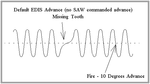
In operation the system is very simple. The crankshaft is fitted with a 36-tooth wheel, with one tooth missing in order to provide crankshaft synchronization. The EDIS system is a wasted-spark setup (i.e. two spark plugs fire which are separated by 360 "cycle-degrees" of a 4-cycle engine), so there is no synchronization with the camshaft. Near the crankwheel (radially-situated from crankwheel centerline with a 0.030 to 0.060 inch gap) is a Variable-Reluctance (VR) sensor - this sensor produces a bi-polar signal very similar to a sine-wave which is generated by the rotating crank wheel. This signal polarity is such that when the tooth tip is exactly pointing to the VR sensor, the resultant VR waveform is at zero potential falling from a positive to a negative polarity - i.e. a zero-crossing with a negative slope. This resultant signal is fed directly into the EDIS module, indicating crankshaft position (every 10 degrees crank). The thing to note here is that the EDIS module handles all VR signal processing. In fact, the EDIS module has a built-in VR signal hysteresis - when the VR signal is transitioning from negative-to-positive polarity (next tooth is approaching), the signal must reach 0.5 volts positive before the EDIS module will "arm". It then will "trigger" when the signal passes back thru zero from a positive-to-negative transistion, when the VR tip is aligned with the crank wheel tooth. We have measurerd and verified the hysteresis effect on the bench (in-circuit). This hysteresis helps prevent false triggering, and it is something to note when experimenting with the EDIS module.
With the VR signal, the EDIS module can synchronize with the engine crankshaft. Note that the missing tooth on the crank wheel indicates the absolute crank position. In practice, the crank wheel and VR sensor is oriented such that the missing tooth occurs 50 degrees before Top Dead Center for the EDIS-8. The EDIS-4 and EDIS-6 modules have different advance settings (need to determine these values from measurement). With this setup, the EDIS module will fire the ignition at 10-degrees advance as a default, unless the module receives a SAW command (discussed below). This 10-degree advance is constant, regardless of RPM. This functions as a limp-mode, in case the module never receives SAW commands from the ECU it will generate a useable (but not optimal) advance to get you home. This is an important feature of this system, and makes it very DIY-friendly and safe on an engine.
Here is a picture of the (simulated) VR signal generated from the crank wheel, and the EDIS-8 firing point for coil #1:
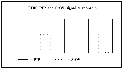
When the EDIS module receives proper VR signal, it generates a 12-volt square-wave signal with a period linked to the next cylinder to fire. In other words when this signal (Ford-named PIP) transistions from +12V to ground, one of the ignition coils are firing. This signal follows the ignition coils, not the VR sensor (as indicated on some incorrect documantation floating around). So, for an EDIS-8 module, there will be four complete cycles of the PIP waveform for evey 360 degrees crankshaft, or thirty-five VR signal cycles (not 36 because of the missing tooth). An EDIS-6 will yield three PIP cycles per every 360-degrees crank, and an EDIS-4 gives two.
This PIP signal is used as a reference to synchronize the generation of the SAW pulse by the ECU (in our case MegaJoltLight). The SAW signal is generated by the ECU and is an input to the EDIS module. This signal is a +5V positive-transitioning pulse, and the width of this pulse determines the advance that the EDIS module will use for subsequent ignition events. Note that the SAW pulse must be synchronized with the PIP negative-transitioning pulse - it cannot be applied asynchronously to the PIP signal, otherwise incorrect advance commands will be interpreted by the EDIS module. Also note that the SAW signal does not have to be sent on every PIP cycle - the EDIS module will remember the last SAW commanded advance and "remember" it for all subsequent ignition advance values until a new pulse is received.
Here is the proper relationship between the two signals:
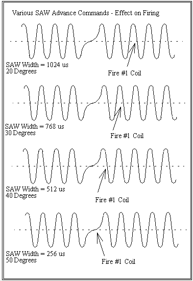
Question - how does the EDIS module obtain the advance value from the SAW signal? Simple - the width of the SAW signal determines the amount of advance generated by the EDIS module. A simple equation governs the width as a function of advance:
SAW (microseconds) = 1536 - (25.6 * Commanded_degrees)
So, the width of the SAW word in degrees is related to the desired advance by the above equation. At first glance, it looks kinda odd, but it does make sense (depending on the hardware generating the width). With a microcontroller timer peripheral, most timers use a counter 16-bits in length, and they have a mode known output-compare, which is used to make an output toggle when the counter reaches a comparison value. So, if one uses a 16-bit timer incrementing at a 1 microsecond rate, and uses a 16-bit comparison register to toggle the output, they can easily generate the required period. In fact, the numbers are quite easy to use - see the following table for example SAW advance widths and corresponding 16-bit timer compare values:
Degrees Width(us) High-order 8-bits : Low-order 8-bits
----------------------------------------------------------------------------------
10 1280 0x05 0x00
20 1024 0x04 0x00
25 896 0x03 0x80
30 768 0x03 0x00
40 512 0x02 0x00
50 256 0x01 0x00
55 128 0x00 0x80
The numbers now make a little more sense. The high-order of the 16-bit timer drives every 10 degrees, and the lower 8-bits drives the advance values in-between. This makes generation of advance widths very easy with a microcontroller. Those Ford engineers knew what they were doing!
The range of advance word is from 59 degrees (60 would be a pulsewidth of zero) down to 0 degrees - all of these have been measured on the bench. How does one measure this? Using a two-channel scope and monitoring the VR waveform and coil #1 output from the EDIS module, it is easy to see the relationship:
The other part of the whole EDIS module is the multiple-coil drivers. First thing is that the EDIS module has the actual ignition coil driver built-in - the driver is not part of the Ford wasted-spark coil pack. The coil packs are just standard ignition coils, and could in theory be substituted with other coil-only packs. The EDIS-8 module has four coil drive channels - EDIS 6 has three, and the EDIS-4 has two. The EDIS module handles the dwell-time automatically, depending on commanded advance and RPM - another feature which makes the EDIS one of the easiest to use DIY setups.
The ordering of coil drive fire for the EDIS-8 is coil A, B, C, D, A, B, C, D, A... - it just round-robins thru each of the coil drives. This is important to know when setting up firing order for the destination engine.
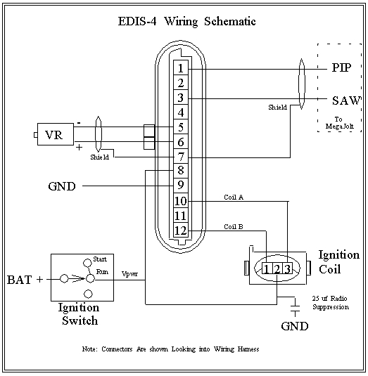
O.K. - we now know enough to implement the EDIS module in an rugged ignition system. The EDIS ignition system is rugged - the module mounts under-hood and will survive engine-bay temperatures, water, freezing, etc. And with only two wires going back to the MegaJoltLight box (PIP and SAW), wiring is extremely easy.
For reference, here are the wiring diagrams for the various EDIS modules, starting with EDIS-4:

ok so thats a mouth full.
Make sence?

The MegaJolt Lite Jr V3

The EDIS 4

more info to come.
Cody