Ausmini
It is currently Fri Apr 19, 2024 12:52 pm

All times are UTC + 10 hours


Post new topic Reply to topic  [ 116 posts ]  Go to page Previous  1 ... 4, 5, 6, 7, 8
Author Message
 Post subject:
PostPosted: Mon May 16, 2011 9:30 pm 
Offline
1098cc
1098cc

Joined: Thu Mar 22, 2007 9:25 pm
Posts: 1322
Location: wooToomba
Definitely the correct switch in the car, just wired up completely incorrectly. :) At least that means it's something I can fix.

Given the mention of the TP832 diagram, I did some searching, and found this thread. Which includes:
Mick wrote:
You should have three wires, Green, Red/Light Green and Brown/Green.

Brown green is on it's own closest to the passenger door (when the motor is mounted in the car), whilst green and Red/Green are side by side inboard of this.
Red/Green is closest to the engine. i think you should also need a black wire to connect the body of the wiper motor to the chassis.

I think that'll get me through! :D

Then, after doing that, I'll install a momentary switch to short from pin 1 (on the switch) to earth, in order to give me a single sweep option. :D That's what I was after originally, when I started wondering about self parking. The option to just push a button and have the wipers do a single sweep, rather than constantly clicking a 42 year old switch. :wink:

And I might - might - maybe - also (later) add a switched resistor (20-25 Ohms) in the earth line, after the short, following DrMini's ideas for the old rectangular boxes... I reckon I could do that for under $10 - that's simpler than trying to rebuild my existing single speed motor into a two speed motor. Or buying a two speed motor. And then rewiring the switches. Again! :roll:

Thanks for the help, guys - I'll post confirmation after I manage to get to rewiring it. :)


Top
 Profile  
 
 Post subject:
PostPosted: Wed May 18, 2011 1:01 pm 
Offline
1098cc
1098cc

Joined: Thu Mar 22, 2007 9:25 pm
Posts: 1322
Location: wooToomba
Well, my post above is wrong. :roll: With a bit more inspection, seems the post that I quoted above is for a different wiring diagram... :? It lists Green, Red (Light Green Trace), and Brown (Green Trace). I think that's the DeLuxe/MiniMatic diagram. I'm guessing, as a Series II Matic, I should be looking at the 1100 Mini Matic/Mini K diagram, which is the same as what Winabbey posted. It has Green (power source), Green (Yellow Trace - to Switch 8 ) and Black (Green Trace - Switch 1 + 7). :?

The main reason I can't just nut out the difference in the wire colours is that the different colours go with different switches. The switches have different numbering to go with the different colours. :shock: :roll:

Also, I've figured out why my wiper motor's done the way it is. :o It's wired as per the diagram for the Mini Standard Saloon. :roll: Who would've thought there'd be so many variations in the wiring diagrams in such a short number of years..? :? The Standard saloon has the same pins as the 1100 Matic, it just doesn't use all of them (and, therefore, I'd guess it didn't self park). :(

I've gone through all my schematics - my book, pdf's, etc. There's heaps out there if I had the Pommy motor, and a little bit more on the two speed 12AUW, but I can't find anything with G/GY/BG that shows which colour goes to which pin on the motor. Any tips would be appreciated. :)


Top
 Profile  
 
 Post subject:
PostPosted: Wed May 18, 2011 2:26 pm 
Offline
1360cc
1360cc
User avatar

Joined: Wed Oct 03, 2007 9:04 pm
Posts: 6651
Location: Melbourne, VIC
Tadhg wrote:
Any tips would be appreciated. :)

Try creating a new thread asking for someone with a working single speed self parking 12AUW to post a picture of the connections or to describe what wire connects where. I'm guessing MK II S and Mini K owners would be candidates. Also ask them to quote the part number on the switch itself.

P.S. Once you get it working please post the solution so others won't have to go through what you have. You can see that my original question about two-speed wiring took quite a while to sort out with contributions from a number of people.

Where's the Doc when you need him? I know, he's absent atm.

_________________
ex-NSW Police 1970 MK II Cooper S
VMCI #43


Top
 Profile  
 
 Post subject:
PostPosted: Wed May 18, 2011 8:28 pm 
Offline
Mods rock!
User avatar

Joined: Fri Oct 03, 2008 9:02 pm
Posts: 5079
The connections are the same as the two speed only the Blue / Green Trace wire is not present (second speed). Back in this thread John Smidt put up the connections to the motor.

_________________
Image


Top
 Profile  
 
 Post subject:
PostPosted: Thu May 19, 2011 1:57 pm 
Offline
1098cc
1098cc

Joined: Thu Mar 22, 2007 9:25 pm
Posts: 1322
Location: wooToomba
Ok - first off, I like posting solutions. :) There's nothing worse than a question where it's clear the problem's been solved, but the solution's not confirmed. :x :roll:

I did think about putting it in a new thread, but, figured we're soooo close... And yes, I'll put everything together and summarize it all when we're done here. :wink:

In that spirit, I went out and tried to wire it up today. And we have... Weirdness. :? I've got Green (Power) going to the single pin (nearest the wheel/street - Pin C on the original photo on this thread). I've got GY (Green Yellow Trace) going from the pin nearest the engine (Pin D) to Switch 8. I've got BG (Black Green Trace) going from the other pin (Pin A) to Switch 1 + 7. I've got the body earthed.

Now, I've made my wiring a bit of a mess - I've got the body earth and the switch earth (switch 6) earthing at the same point (couldn't find where else there was a handy earth, so it's earthed on the high beam foot switch). I've also hacked into my wiring, creating a point to add a switch between Switch 1 and Switch 6 (as a momentary wiper switch - just got to decide where to locate it - maybe on the column, maybe on my yet-to-be-fabricated dash). And I've re-used the existing Red wire in place of the BG wire. So my wiring's not exactly pretty... :oops: Plus, though I've described the pin connections as I currently have them, that's not how they started out. :oops: I originally had BG going to Pin D and GY going to Pin A - I thought that was more like the 2 speed wiring. With that arrangement, I turned the wipers on and they parked. Then they wouldn't move anymore. :oops: :lol:

So, I think I've got it wired correctly. :) The weirdness is that, if I flick the power so that the switch is off when the wipers are still on the up stroke, they immediately park wherever they are. :? But if I switch them off on the downstroke, they park after they hit the end of the sweep. :) If I flick them just after the top of the sweep, they'll stop at the bottom. :) If I turn them off close to the bottom, they may end up halfway up the screen again! :shock: Is this normal..? :? I've honestly never used self-parking Mini wipers before. :oops: :lol:


Top
 Profile  
 
 Post subject:
PostPosted: Sat May 21, 2011 12:22 pm 
Offline
1098cc
1098cc

Joined: Thu Mar 22, 2007 9:25 pm
Posts: 1322
Location: wooToomba
Ok, I think I might have the problem half sussed now. :? But to review!

My wiring set up is now:
. Green Power -> Wiper Motor pin nearest left wheel.
. GY (Green Yellow trace) - Wiper Motor pin nearest Engine -> Switch Pin 8.
. BG (Black Green trace) - Wiper Motor pin nearest passenger - > Switch Pins 1 + 7.
. Black - Wiper Body -> Earth
. Black - Switch 6 -> Earth

The connections at the Wiper Motor pins I'm not 100% certain are as per the book, but they work best. The connections at the Switch are as per the book. :wink:

I have wipers that park. :) But they park between half way up the screen or, if I switch off on the upsweep, it'll stop at the top of the sweep. :? Not at the bottom of the sweep. This doesn't look very good! :(

I've had a couple of ideas why this may be the case. One crazy thought that crossed my mind is that maybe the break in connection (current) on the park ring is offset to one side, and, that, with the change from positive to negative earth, the motor's now spinning the other direction, so the park is slightly up the screen, rather than slightly down the screen (if you catch what I mean). :? So I switched the earth and power sources on the wiper motor, but that didn't work. :roll:

The only other idea I've got is that perhaps what DrMini describes below has been done.
drmini in aust wrote:
You can make the round motor (1 or 2 speed) park on RH side simply by turning the drive pin plate 180° on the plastic gear.
I tried this and it works. :wink:

Does this sound plausible..? My wiper motor has been refurbished (not by me, PO organized it, could've been done by anyone), so it's quite possible that, when the park ring was replaced, the wheel was reassembled incorrectly. :? Are there any tricks to getting the drive pin plate off? I don't want to snap the plastic... Do I need to remove the wheel assembly from the box..? That may sound like a lazy question, and it probably is, but I'm getting tired of pulling the wiper motor out... :roll:

Any tips would be appreciated. :) And, to mirror Winabbey's sentiments... Where's the Doc when you need him? :lol: He's the one who suggests turning these things into RH Parkers by moving the drive pin plate. And yeah, I too realize he's spending time with his family and/or has computer issues.


Top
 Profile  
 
 Post subject:
PostPosted: Mon May 23, 2011 1:02 pm 
Offline
1098cc
1098cc

Joined: Thu Mar 22, 2007 9:25 pm
Posts: 1322
Location: wooToomba
Well, I went out and pulled the motor again this morning. :) Getting better at it - only took me 1.5 hours from beginning to end this time - last time it was more like 2 hours. :oops: I parked the wipers where I wanted them (by cutting the power, not with the switch), I pulled the drive wheel, checked to make sure the pin was on correctly, changed the wheel position a little, reassembled, and... Well, I'll give detail first! :P

First thing I did was make sure the Park Ring and Crank Pin were correct relative to each other. :) My belief is that the Drive Wheel Crank Pin's got to be 180º from the park notch in the park ring to park on the left. Thankfully, this was already true, so I didn't have to risk ruining the wheel in an attempt to fix it. :oops: :lol: 
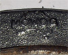
I then located the numbers on the Drive Plate (numbers 321) directly over the park pins. This meant that the notch in the Ring was located over the fingers, in order to park the wipers there, and the wipers were stopped where they were to be parked. :)

So, with the internals of the wiper box all where I thought they should be, I reinstalled the motor. Just as I finished doing that, I decided that, if I ever have to do it again, I'm going to glue the little nylon washers onto the bottom of the wiper motor... They're such a pain to hold in place! :x :roll: Eventually got it done. Turned the car on... Nothing. :? Forgot to hook up the power. :oops: Did that, and...

Success! :o Initially. Sort of. :( Wipers parked exactly at the bottom, just as you'd want them to. :D They also parked 2/3 of the way up the screen on the upward sweep. :? I left the car, typed most of this post, went back out, and failure. :? :cry: :roll: The wipers are now only parking just before the top of the sweep, they're not parking at the bottom at all. :x :?

At least I can confirm one thing - if you short pin 1 to pin 6 through a momentary switch, you can give yourself a single push sweep of the screen. :) So at least that small part of my plan is working out... :roll:

I've got photos, everything except how to disassemble the plastic gear/drive pin/park plate. I do plan to try and do up a 'How To' sort of thing, condensing all the info from this thread into a single resource. But I can't really do that until I've proved that I have half a clue, and that won't be proven until my wipers are parking at the left. :(

Can anyone confirm the way the park ring is supposed to sit relative to the crank pin? I've got them 180º offset from each other. I can't see why the wipers are parking where they're parking - it makes no sense to me. :oops: :(


Top
 Profile  
 
 Post subject:
PostPosted: Mon May 23, 2011 4:45 pm 
Offline
Mods rock!
User avatar

Joined: Fri Oct 03, 2008 9:02 pm
Posts: 5079
Hi Tadhg,

I've been a bit tied up and haven't been able to get to this, however, hopefully, this will sort you.

This pic shows the wiring to the motor, for a 2 speed motor. The single speeder is the same orientation, however the blue wire with green trace is not used (2nd speed).

Image

The earlier cars did not have the multi pin conector, just single wires, but all went in the same place. Don't forget too, that the body of the motor needs to be earthed (which I noted somewhere that you've already done).


This is the contacts that slide on the back of the gearwheel contact. The little pips on the ends of these often wear and 'disappear'. When that happens, they make intermittend or poor contact with the rotating contatct on the back of the gearwheel. This I susupect could be the problem with yours.

Image


This is the Gearwheel

Image


And this is the orientation of the revolving contact on the back for LH Park (Note the pin is at the top)

Image

Also check that you don't have a wobble in the gearwheel, as this will cause loss of contact too.

The way these things are designed and made, if all parts are in good order it is ONLY possible for them to park in one position and that depends on the orietation of the revolving contact with respect to the pin (on the other side) om the main gearwheel.

_________________
Image


Last edited by GT mowog on Mon May 23, 2011 5:00 pm, edited 1 time in total.

Top
 Profile  
 
 Post subject:
PostPosted: Mon May 23, 2011 4:56 pm 
Offline
1360cc
1360cc
User avatar

Joined: Wed Oct 03, 2007 9:04 pm
Posts: 6651
Location: Melbourne, VIC
I can see a clear and concise sticky with good pictures and diagrams on identifyng, dismantling, checking, refurbishing and reassembling both single and two speed versions as a great bonus for the forum. Pictures of motor and switch part numbers, connections and wiring diagrams with colour coding would complete the picture. The good thing is I think we are almost there. :)

P.S. John is in the business of restoring Mini wiper motors and boxes so I don't think it would be good etiquette to ask him for more detailed help.

_________________
ex-NSW Police 1970 MK II Cooper S
VMCI #43


Top
 Profile  
 
 Post subject:
PostPosted: Mon May 23, 2011 6:30 pm 
Offline
1098cc
1098cc

Joined: Thu Mar 22, 2007 9:25 pm
Posts: 1322
Location: wooToomba
Thanks GT! :D Gotta say, your photos are much, much clearer than the ones I took with my old iPhone 3G. 8) Didn't want to get into trouble for taking out the DSLR with greasy hands. :oops: I've thoroughly packed the top end of my wiper motor with grease (where the cable comes in - pretty sure that was recommended pretty early in the thread as one of the waterproofing ideas), hence the rather greasy hands. :wink: Gotta ask, though - where's your Ø6 drain hole? :lol: Pleasingly, I had less staining at the bottom of my wheelbox than the one you've shown. :o

Well, I went out again a little while ago (been getting this post right for a while :oops: ). I tried the wipers again. They parked properly. :shock: :? They still wanted to park in the middle of the sweep (near the top of the up sweep), but they stopped at the bottom again. Given the difference when I shorted Pin 1 to Pin 6 earlier (parking ONLY near the top of the upsweep, and continuing past the park point), and given I've done nothing since... :? All I can guess is that wheel wobble's the problem. :roll: :) If I leave the switch on, it flies through the point where it parks (on the upsweep) without any noticeable difference, so any wobble's only affecting the outer fingers (park fingers) - which makes sense, given they're further from the centreline of the wheel, meaning that any wobble will be more noticeable the greater the radius. Beyond that, if I flick the switch off just before the point up the sweep where it self parks, there's something of a whirring coming from the motor. A whirring like it's trying to spin, but just doesn't have the current. Which fits with the idea of wheel wobble. Might pop the cover again soon and give the gear wheel a gentle tap. :)

One good thing that I can take from the photos is that my gear wheel's correct. The crank pin's 180º from the park ring notch, as shown. :) I'll also note that my gear wheel is a 110º wheel. I'm guessing that's no big deal. :)

Winabbey, you're right - not far from a full 'How To' now! :D I'll start looking at putting together a proposal for it soon. :)


Top
 Profile  
 
 Post subject:
PostPosted: Sat Sep 01, 2012 4:42 pm 
Offline
MinisPlus
User avatar

Joined: Mon Jul 27, 2009 10:12 pm
Posts: 172
Location: Mooroolbark, Vic
I adapted a 3442A switch to work with my 2 speed motor today.

I had a few of these about, and after a bit of checking and testing found that by simply adding a wire between
pin 6 (low speed) and pin 1 it works perfectly and parks.

The rest of the wiring remains exactly as previously mentioned in this thread and the sticky.

Also repaired the worn contacts that rub on the park plate by soldering new pieces of copper on to the pads and turned the park plate upside down. The top was pitted and the bottom good. Everything works very well now :D

Hope this helps others out there!

_________________
How can it be rusty when it's covered in so much oil?


Top
 Profile  
 
Display posts from previous:  Sort by  
Post new topic Reply to topic  [ 116 posts ]  Go to page Previous  1 ... 4, 5, 6, 7, 8

All times are UTC + 10 hours


Who is online

Users browsing this forum: No registered users and 20 guests


You cannot post new topics in this forum
You cannot reply to topics in this forum
You cannot edit your posts in this forum
You cannot delete your posts in this forum
You cannot post attachments in this forum

Jump to:  

© 2016 Ausmini. All garage work involves equal measures of enthusiasm, ingenuity and a fair degree of irresponsibility.