Edit: 5/9/2017
All of this information and more about my foray into EFI on my Mini is on
my blog. Car is now sold, but I will answer any questions that you leave in the comments section on my blog.
This is part I - the ignition side of the installation.
Part II the EFI side starts here:
http://www.ausmini.com/forums/viewtopic.php?t=67644&start=32Part III the tuning of EFI starts here:
http://www.ausmini.com/forums/viewtopic.php?p=791946#791946Hi, if you didn't already know, I'm attempting to convert my '68 A+ 1310 to run Throttle Body Injection utilising the existing HIF44 by using a Patton Machinery carburettor adaptor
http://www.pattonmachine.com/Carbs-and-Adapters.htm. This is
not meant to be a 'How To', rather a chronicle of my installation.
I purchased a MegaSquirt-II Engine Management System w/PCB3.0 as a Unassembled Kit several months ago. Having a background in electronics/software engineering which has stead me well in building and configuring the Megasquirt (hopefully).
I will initially, (in Part I), will be just get going the ignition wasted spark (EDIS) side going as well as the Megasquirt controlling the thermostatic radiator fan that I'll be mounting in the inner guard. I will not be re-fitting the engine fan.
I welcome any helpful comments, constructive criticism or hints.
 Day 1:
Sorry no photos were taken on this day.
Removed Dissy, leads and all related wiring;
Removed non-resistor spark plugs (Need resistor plugs for ECU installations);
Removed radiator (sounds easy, but wasn't );
Removed radiator Fan... tossed it, won't be needing it again!;
Degreased and cleaned radiator with my Kärcher as it fins were very blocked, couldn't find the right size pop-rivets in my supplies to re-fit the side bracket that has come away;
Degreased engine bay area;
Drilled some holes in my stock air cleaner housing to allow for better breathing (that the theory anyway);
Fitted coupling on air cleaner for the IAC (Idle Air Control)
Day 2:Fixed Radiator shroud, and pop-riveted it back together;
Removed starter motor to gain access to the ring gear on the flywheel so I could 'lock' the engine so I could remove the harmonic balancer engine bolt. I locked it by jamming a cold chisel between the ring gear and housing;
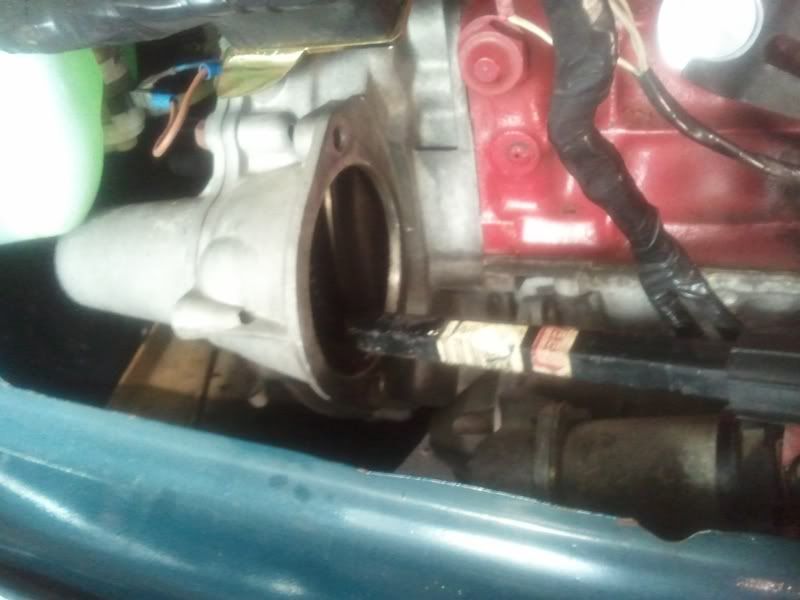
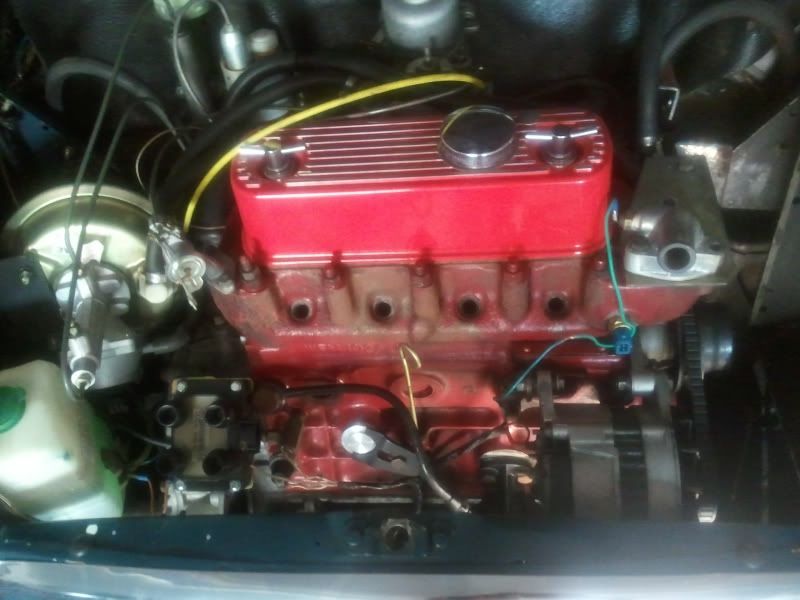
Removed left hand engine mount to gain access to the front pulley and the engine bolt. Boy was the bolt on tight, ended bending my you-beaut 'chrome vanadium' bar. Notice in the picture, that the bolt has a lot of loctite on it, maybe that's why it was so tight; 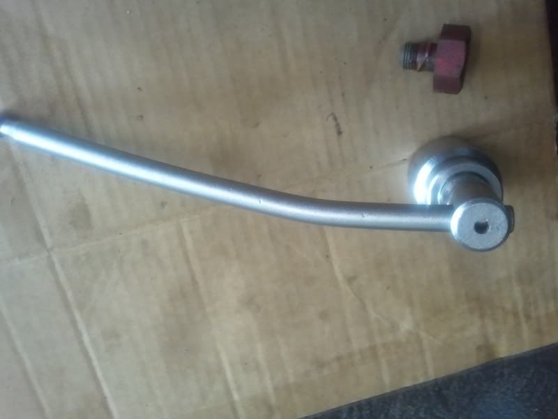
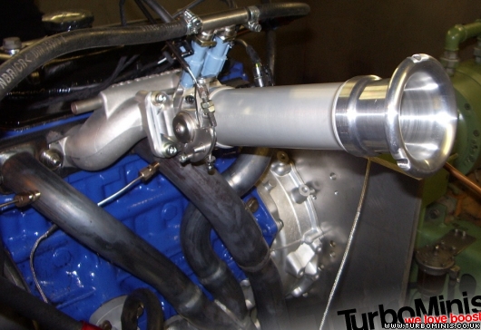
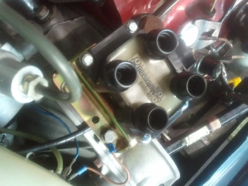
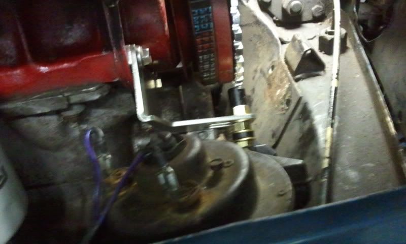
Fitted the Motorcraft (Ford) EDIS coil and bracket to the wok;
Not fitted today and only needed for the 'fuel' side of this installation, is a Throttle Position Sensor (TPS);
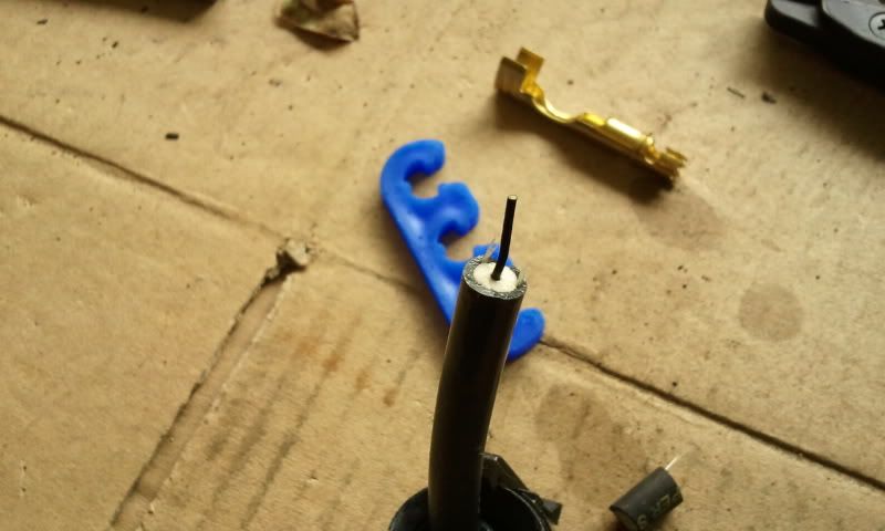
The sensor...
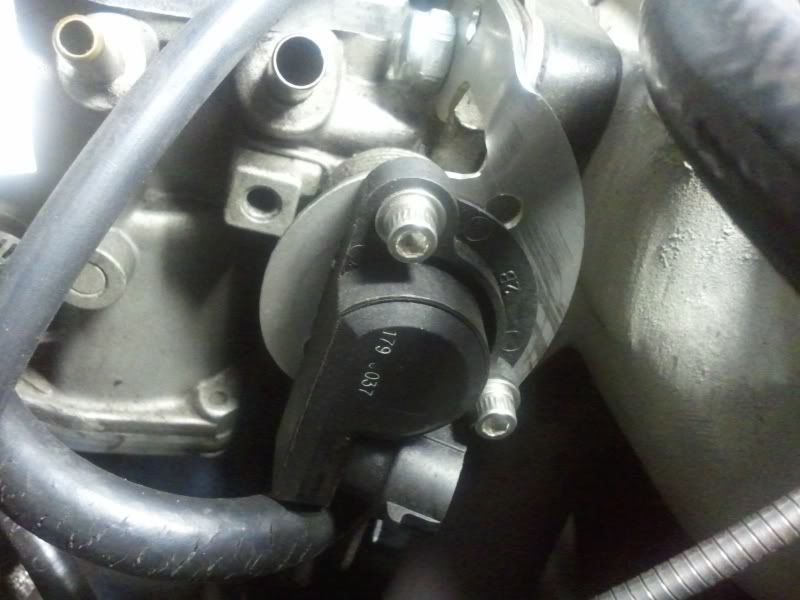
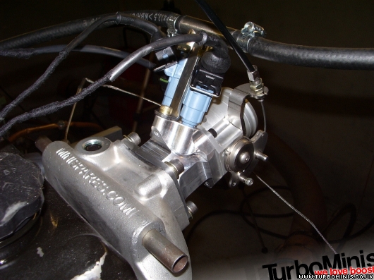
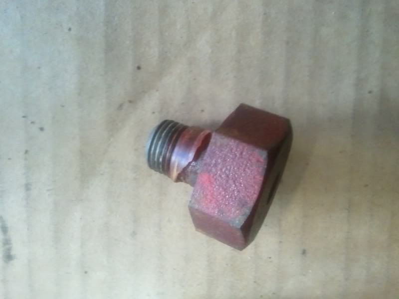
The special brass coupling...
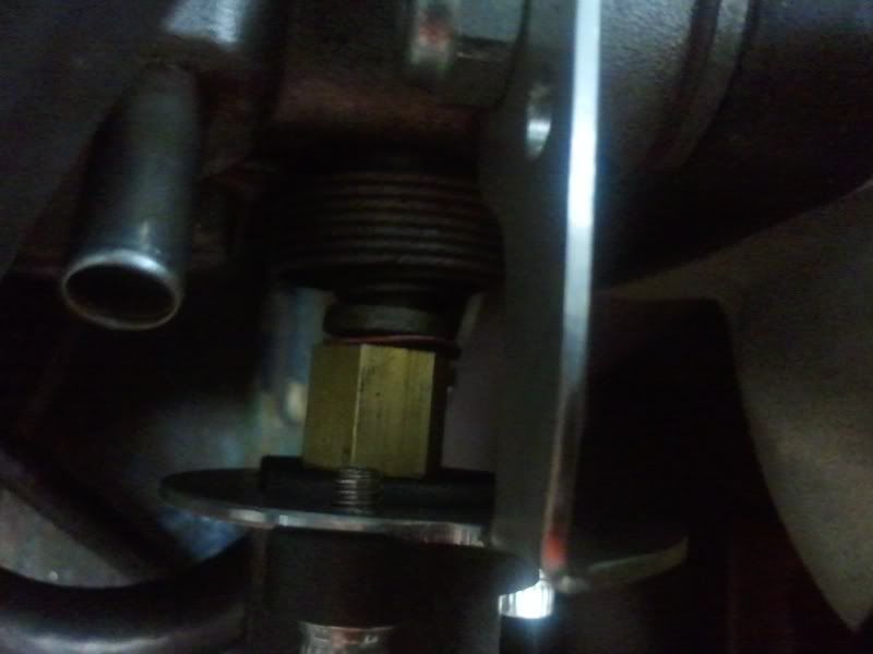
Fitted distributor blanking plug a friend lathed up for me, after removing distrubutor drive gear thingy. Plug is visible in this photo;
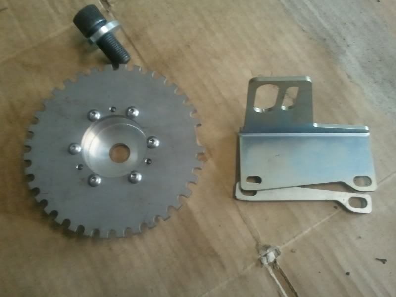
Tomorrow:Hopefully I'll fit the trigger wheel and bracket amongst other things...
 Day 3:
Not much today. Just fitted the trigger wheel and loctited the new front pulley bolt after I borrowed a stronger breaker bar from Mick (thanks Mick). Yesterdays bent breaker bar was a Sidchrome one I have been using for the last 30+ years. Maybe I have gotten stronger with age. 
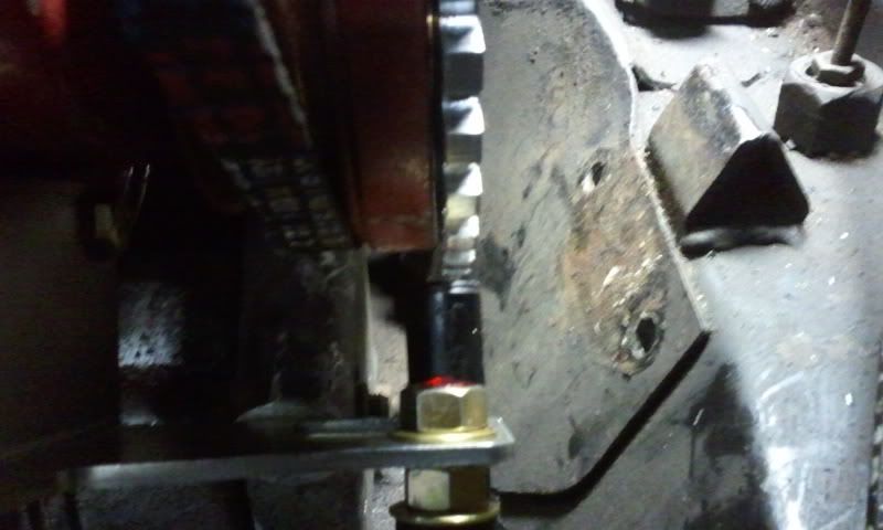
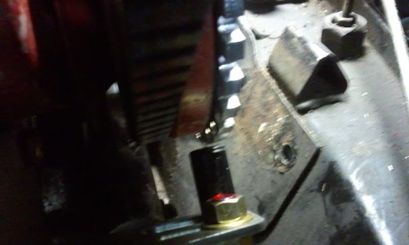
Some pictures of the trigger wheel and VR sensor.
Tommorow:Not sure, might put thermostatic fan on and if enough time wire the spark plug leads. To be continued...
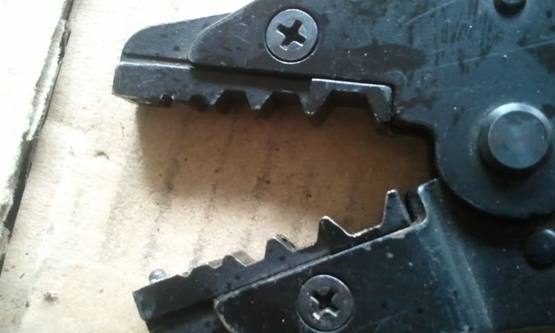
Day 4:Not a lot of progress today. Wasted time out on the road looking for a crimp tool for ignition wire... ended up ordering on Ebay tonight after
MINImal effort found one for me. Thanks.
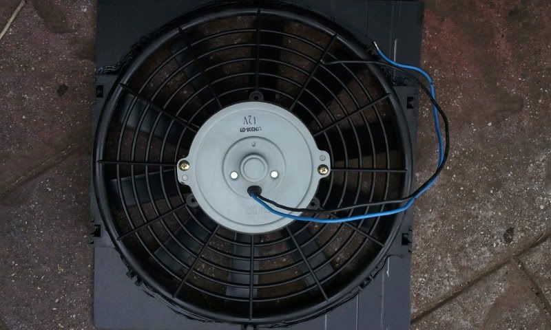
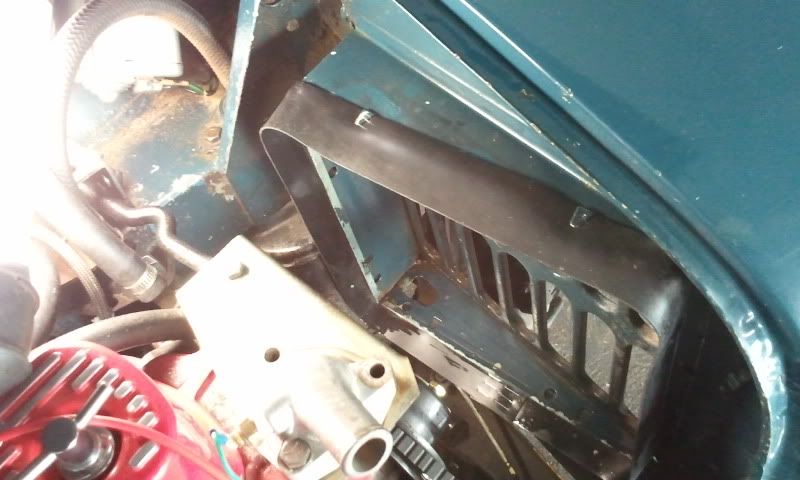
Created a shroud for the thermo fan, so It will only suck air through the radiator, rather than the sides. Thanks to Mick for this tip.
Eddie was helping also.

Fitted 40mm rubber strip around radiator shroud (get it from Clarke Rubber) to also seal against leaks.
Spent some of this evening crimping and solder all the connectors for the sensors e.g. IAT, CTS, TPS, VR, coil pack and IAC. Whew don't you just love acronyms. Need to get connectors for the CTS and IAT, had some but can't find; don't need straight away as they are not required for the "ignition only" phase.
TomorowFit radiator and thermo fan. Install Megasquirt Relay Board, and Megasquirt. Start the wiring in car. Maybe, just maybe will turn it over; if not definitely Saturday.
Day 5:
Fitted the fan and shroud to underside of wheel arch, tested the fan and also made sure wheel wouldn't rub on full lock;
Refitted the radiator and discovered it's shroud was rubbing on the timing cover vent thingy me bob. So did some creative panel beating. Could this have been a source of rubbing and noise... time will tell. What a pain in the fanny it is putting the bolts back in. Luckily my son Hamish helped me;
On the way back this morning I called into a auto electrician to see if he could crimp the spark plug leads. He didn't have a crimper,  but he gave me an idea for a work around which I'll try out, if it works I'll post the details;
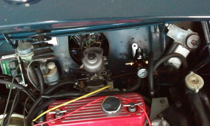
Here you can see radiator is back in, as well as I have placed the fuel regulator in the approximate position.
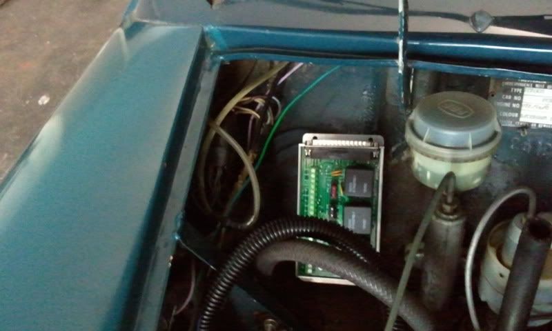
Here you can see the Megasquirt relay board approximately placed.
Tonight I will finish wiring the final two missing connectors for the CTS and IAT which I picked up from EFI Hardware in Mitcham this morning.
Tomorrow:
Finish wiring all sensors, (this will mean all sensors required for ignition as well as fuel injection will be done), locate and fix Megasquirt and Relay board as well as the TechEdge wideband. Fit spark plug leads, start car (hopefully) and adjust base timing.
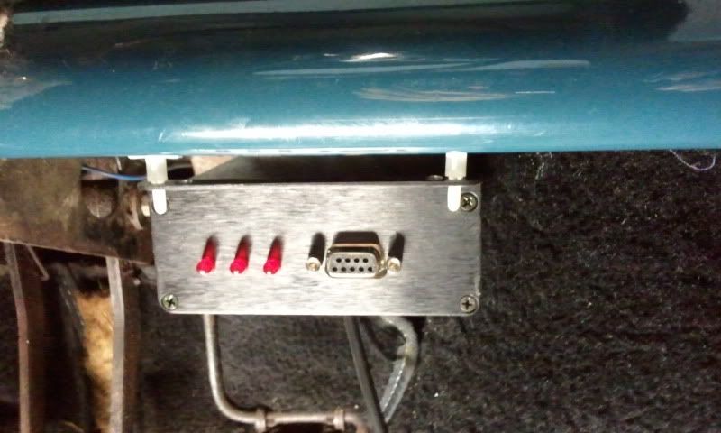
Day 6:Not a lot of progress. Fitted the MS under the dash. What a pain in the bleep that was. Very little room to see what your doing and to get a drill in there etc;
Could only use 3 of the 4 mounting holes. I used PCB standoffs and made a tool that can be pressed over them to do a quick release which is basically a metal rod with a 3mm hole. Time will tell if the standoff's are robust enough. I wanted the RS-232 port to be easily accessible for my RS-232 to Bluetooth converter used for communication with the MS IE on the fly tuning, firmware updates and the tuner studio software.
Here is the MS fitted under the drivers side dash.
Fitted the MS Relay board over the Heater blanking plate on the drivers side bulkhead, using 25mm high 3mm tapped standoffs. Drilled a hole in blanking plate for the MS to Relay interface cable. Tip: the surface on the bulkhead is not flat, so only use 3 standoffs, and re-drill the single hole in the between the 2 original holes.
Today/Tommorow:Today I think I'll have a Mental Health break. Tomorrow I should have enough time (famous last words) to complete the wiring and start her up.
 Day 7
Day 7Added this yesterday but some how it got mysteriously deleted?! Sorry for the confusion. 
Modified the MS and MS relay board to allow it to support two ignition wires for the EDIS4 coilpack;
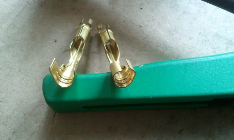
Crimped the coilpack special connector ends;
Tomorrow
Connect sensors to Relay Board, turn ignition key and Vroooooooom.
Day 8/9:Well... spent all of yesterday afternoon trying to get it started after I finished looming and connecting the sensors.
Symptom were no spark, except once when it backfired. Using the TunnerStudio ignition logger/tooth logger under the diagnostic tab, I ascertained that it was a trigger problem. After much cranking to look at the problem, my battery went flat. Autobarn had a special on 600, 900 & 2400 Amp jump starter packs; I opted for the 900A (I think its 450CCA) and put it to good use for the rest of the arvo.
I got real techo and pressed my DSO (Digital Storage Oscilloscope) into action. Looking at the waveforms it was very apparent the VR sensor was not sensing the missing tooth properly, in fact it was getting 2 missing teeth instead of 1, hence the MS ECU was not firing the coil pack because it was not being indexed properly ie 1 missing tooth 35 teeth and repeat.
Fast forward to this morning. Had a look at the VR sensor and how it was positioned. The VR sensor was slightly out by around 2.5mm in the Z /axis (looking from front of pulley Z is in out, X left/right and Y is up/down) and around 3mm in the X axis. Also re-adjusted the air-gap back to 1mm (Y axis).
Back to the diagnostic "tooth logger", things looked a lot better, but it was getting an occasional missing tooth. I adjusted the Zero-Crossing
Setpoint and Hysteresis (R56 & R52) multi-turn potentiometers whilst cranking and monitoring the output of the voltage comparator U7a with the DSO, and as they say, "bingo!" a perfect waveform.
I also noticed now that the red ignition LED was lighting when cranking, so now I should be able start her up... so I thought. Screwed the spark plugs in, and gave it a crank... nothing. 
Connected the DSO to one of the ignition outputs on the MS relay board (there are 2 for a wasted spark coil on a 4 cylinder engine) and it was toggling as it should. Had a look at the 12V going to the coil... not there. Looks like I blew it yesterday whilst fiddling with the wires on the Relay board.
Replaced fuse, surely (don't call me Shirley) it will start now... nope, nothing, SFA.  Brainwave, maybe I have the two coil wires transposed? Changed the wires around and then crank... Vrooooooom, Vroooooooom.
Let car warm up so I could test thermostatic fan. I'm controlling this from the MS ECU via an relay mounted on the bulkhead. Got the temp up to the turn on point (initially set to 85C with 5C hysteresis) but no fan... bugger. Looking at the voltages to the relay, it was soon apparent that I had stuffed up again. On the relay board I'm using the "Fast Idle Relay" to control my fan relay. It has a jumper which allows you to either supply 0v or 12V I for some reason choose 0V. Removed and re-soldered link ito the 12V position. Kalamazoo, shabam, we now have a thermo fan that works under ECU control very well!
Edit: Nearly forgot, the car would keep running when I turned off the ignition! Long story short, I had to put a diode in series with the alternator ignition idiot light. I just plumbed one into the lead that went to the alternator.
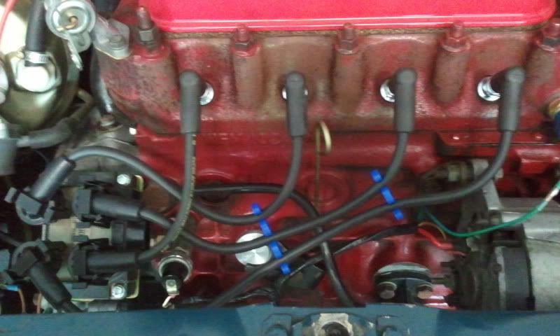
What an unexpected difference the new ignition has made to the performance and 'feel" of the car. It starts easier, seems to have more low down torque and revs more freely. I'm only using a best guess map until I can get some on the road time to tune it a little better.
Stay tuned for further updates. The car is now all wired and ready for the EFI, all I have to do is put in the EFI fuel tank along with a fuel return line, and then I'll have a TBI mini! Hope to do all of this in early January, so stay tuned.
[/url]