OK, this is how you do it.
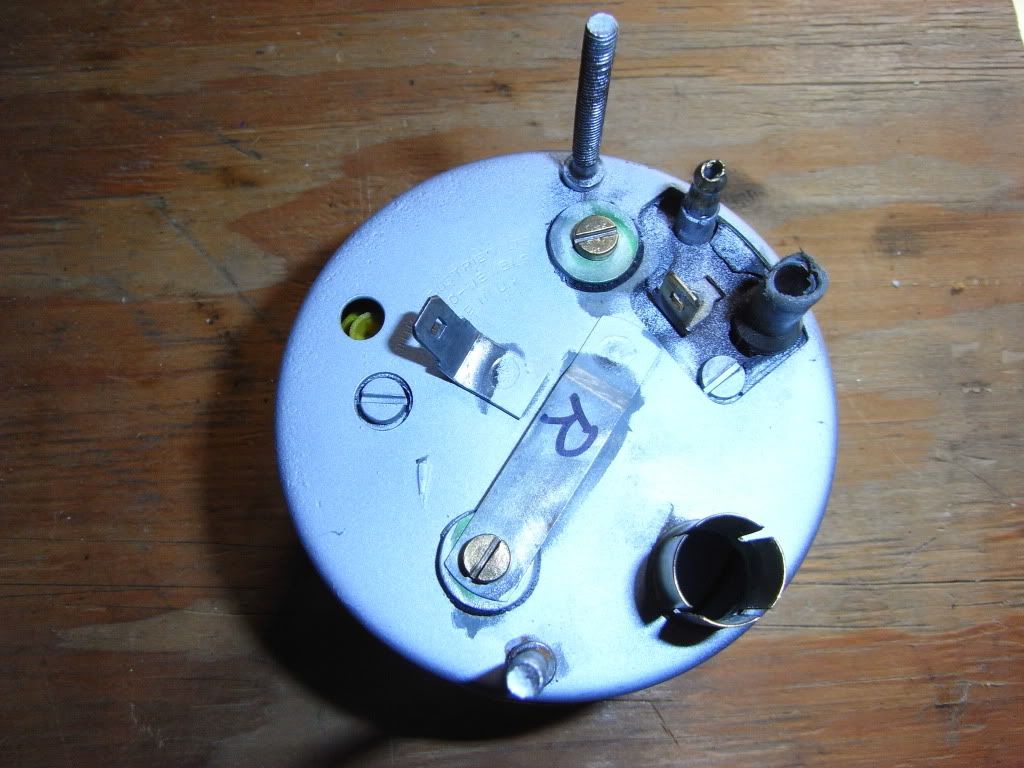
The spade connector on the tach which is spot welded to the back casing is earth. The other spade connector should be connected to fused, switched power (connect this as described below).
The two bullet terminals are signal-in and signal-out. The way the RVI tach works is a little different to modern tachs; it senses the current drawn by the coil as it charges before each cylinder fires. These two terminals must be connected in series with the power feed to the coil.
This power feed to the coil comes from the switched side of the fuse block. I removed this wire, and made up a wire with a male spade terminal one end and bullet the other (I don't remember whether it was male or female now, you'll have to experiment to find out). This was attached to the coil power wire, and to the signal-out bullet terminal on the tach.
I then ran another new wire from the terminal on the fuse block to which the coil feed was connected, and ran this wire back to the tach and connected it to the spade terminal mentioned earlier, and ran a short loop to the signal-in bullet terminal.
Confused yet?
Basically, it's switched power from the fuse block to the tach power-in and signal-in, then tach signal-out to the coil power line which you detached from the fuse block.
Let me know if this is too confusing and I'll draw a diagram