tracytracey wrote:
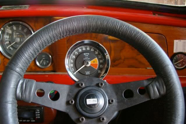
I have a tacho the same as this, can you tell me how the wiring goes? Cheers.
Sure, I'll give it a go..

There are two types of tachs which look like mine: RVI (current sensing) and RVC (voltage sensing). You can tell which you have as it's fine-printed on the tacho face.
If you have an RVC, this wires up just like any other modern tach. Switched, fused +12V power, ground, and the sense wire from the coil -ve terminal (plus lighting if you have it). This tach detects the voltage change at the coil when the points open.
The older RVI type is a little more complex, but still not rocket surgery. Rather than detecting the voltage change when the points open, this tach measures the current drawn by the coil when it charges after the points close.
Before the tach is installed, your coil is wired up as follows:
Ign-switch --> fuse panel --> coil +ve
With the tach installed, this is modified as:
Ign-switch --> fuse panel --> tach-input --> tach-output --> coil +ve
The RVI-type tach has four connections: +12V power, Ground, Sense-in and Sense-out. You basically run two wires (not including the ground wire) from the tach to the fuse block -- one connected to +12V power-in and Sense-in on the tach, and the other to Sense-out. At the fuse block, you disconnect the coil, attach that wire to the sense-out lead from the tach, and plug the +12V/sense-in wire to the terminal from which you took the coil power line.
What this does is route the power feed to the coil through the tachometer first, so it can measure the current drawn by the coil when it charges.
On mine, the sense terminals were a male and female bullet -- I don't remember which was which, but it won't hurt if you get them backwards; you'll know if it's wrong because the tachometer will try and read backwards
(Since I installed it, mine has been converted with electronic guts as the germanium transistor in mine expired of old age, and it was just easier to replace the guts than try to fix it).
Hope that helps, if I can help explain it a bit more clearly let me know