ausmini
https://www.ausmini.com/forums/

Distributor drive position
https://www.ausmini.com/forums/viewtopic.php?f=2&t=75194
Page 1 of 2

Author:  phillb [ Fri Jan 27, 2012 11:30 am ]
Post subject:  Distributor drive position

Could someone please confirm what the correct installed position of the dissy drive is at TDC with 1 on comp stroke.

Two manuals I have seem to contradict one another.

The Leyland manual (black book) says that the illustration (shown below) is the position you need prior to inserting and rotating the drive.

Image

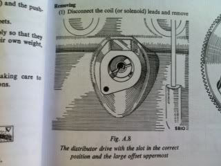
It says to hold the spindle in position shown in Fig A.8 and enter the gear.

The SP manual shows the same illustrated position but states it shows the installed position.

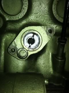
Or perhaps someone could confirm approx where the rotor arm should be pointing at TDC (comp on 1). Mine seems to be at about 1 o'clock.

The reason I ask is that I suspect my dissy is wrongly oriented. Last time I bought a set of leads that were custom length for a mini they were all over the shop.

Cheers

Author:  drmini in aust [ Fri Jan 27, 2012 11:35 am ]
Post subject: 

That pic is the way it should point when installed, AFTER you have rotated the engine 1 full turn from lining the timing dots up.
If you don't turn it 1 turn, the dizzy will be 180° out.
Manuals do not mention this.
It is a glitch in all the workshop manuals, because they all just copied the BMC original (which was wrong).

Author:  TheMiniMan [ Fri Jan 27, 2012 11:47 am ]
Post subject: 

Rotor should be pointing at (roughly) 1-oclock with engine at TDC 9firing stroke on Number 1 cyl)

that means the # 1 piston is at the top,,, the timing marks on the flywheel should have the pointer at the 1/4 mark,,, & the valves on number one cyl should both have clearance,,, & the valves on #4 cyl should be "on the rock" (one is half open & the other is half closed)

that`s it,,, many things there for you to absolutley make sure you have it set-up correctly, so you really can`t stuff it up hey?

Now,,, in saying all that,,, sometimes i`ve seen dizzys have been ripped apart for re-newal/reco/clean-ups etc & they have been put back together one-eighty (180deg) out, so even tho the engine could have been set-up correctly,,, once "that" dizzy goes back in the hole you are now 180 out

get it?

Some people do`nt realise that there are 2x shafts inside the dizzy & once ripped apart they can be set back up 180deg out

Not saying that yours is that way,,, just saying that it can be a catch for the un-initiated :-)

Soooo,,,, whether your "Drive" shaft is set-up right or not,,, you may still have trouble with the rotor pointing the right way (or not) once the dizzy is fitted & this may well be the reason

Got it???

Author:  Timbo [ Fri Jan 27, 2012 11:58 am ]
Post subject: 

I'm going to print this thread out and staple it into my manual. Every engine I've assembled has come out with the distributor 180° out!

Tim

Author:  phillb [ Fri Jan 27, 2012 12:20 pm ]
Post subject: 

Yes thanks Guys. Matt thanks for that I double checked and made sure I am at TDC with 1 all closed and 4 "on the rock".

Ok here is a pic of my spindle (hard to tell but the large offset is to the left).

ImageImage

So comparing with the manual's illustration it seems my drive is anti clockwise to where it should be.

Could that mean it has been installed 1 tooth out?

Author:  drmini in aust [ Fri Jan 27, 2012 12:24 pm ]
Post subject: 

Yes it is but as long as dizzy body is anticlockwise by the same amount it's no biggie.

Author:  simon k [ Fri Jan 27, 2012 1:04 pm ]
Post subject: 

what's a distributor drive? I don't think I have one of them....

Author:  phillb [ Fri Jan 27, 2012 1:05 pm ]
Post subject: 

drmini in aust wrote:
Yes it is but as long as dizzy body is anticlockwise by the same amount it's no biggie.


Ok cheers Doc. I understand it's not a big deal but last time I bought a nice set of leads specifically tailored for mini I had to trim them to make them fit neat.

...and I'd probably be in the same boat with an original dissy and/or lead set, the lengths would be out.

So I basically was trying to figure if it was actually correct or not.

Thanks heaps.

Author:  Morris 1100 [ Fri Jan 27, 2012 1:07 pm ]
Post subject: 

If you do feel the need to fix it make sure you don't drop the drive into the gearbox.

Author:  phillb [ Fri Jan 27, 2012 1:43 pm ]
Post subject: 

Morris 1100 wrote:
If you do feel the need to fix it make sure you don't drop the drive into the gearbox.


Yes, thanks, I know. I need to use a long 5/16 bolt correct?

Do I need to unbolt the distributor housing from the block first before extracting the drive?

Author:  simon k [ Fri Jan 27, 2012 1:47 pm ]
Post subject: 

phillb wrote:
Morris 1100 wrote:
If you do feel the need to fix it make sure you don't drop the drive into the gearbox.


Yes, thanks, I know. I need to use a long 5/16 bolt correct?

Do I need to unbolt the distributor housing from the block first before extracting the drive?


yes, and yes

the best bolts are the long ones that go through the engine mount thing on the radiator end of the gearbox.... basically you can't use a bolt that's too long for the job, but you can definitely use one that's too short

Author:  phillb [ Sun Jun 16, 2013 2:25 pm ]
Post subject: 

simon k wrote:
phillb wrote:
Morris 1100 wrote:
If you do feel the need to fix it make sure you don't drop the drive into the gearbox.


Yes, thanks, I know. I need to use a long 5/16 bolt correct?

Do I need to unbolt the distributor housing from the block first before extracting the drive?


yes, and yes

the best bolts are the long ones that go through the engine mount thing on the radiator end of the gearbox.... basically you can't use a bolt that's too long for the job, but you can definitely use one that's too short


I'm nearly ready to swap distributors and fix the out of position drive at the same time.

I don't have any spare engine mount bolts so I looked at Bunnings but they only have long 5/16 bolts in UNC not UNF. I assume I would need a UNF one.

Any suggestions where to find a suitable bolt?.

Cheers

Author:  mini_mad_matt [ Sun Jun 16, 2013 2:48 pm ]
Post subject: 

You could just make sure 1 of the engine mount bracket bolts are tight and take the other one out.

I'm pretty sure they are the only suitable bolts you will find on the whole car

Author:  drmini in aust [ Sun Jun 16, 2013 3:29 pm ]
Post subject: 

You can also use the 5/16" rocker studs (the long end ones).

Author:  simon k [ Sun Jun 16, 2013 5:58 pm ]
Post subject: 

mini_mad_matt wrote:
You could just make sure 1 of the engine mount bracket bolts are tight and take the other one out.

I'm pretty sure they are the only suitable bolts you will find on the whole car


hydrolastic top tower bolts ;)

or go to a bolt shop, or weld a bit of rod on to a short bolt

Page 1 of 2 All times are UTC + 10 hours
Powered by phpBB® Forum Software © phpBB Group
http://www.phpbb.com/