CHAPTER 12.....The Mini Steering
Hi Guys,
Well it's time for an update. I have been very busy lately doing other stuff besides The Cat. I have spent a couple of hours working on JC's Mini 'Hefty' and Tony's Mini 'Barbie'. I have also gone out and bought another mini, this makes three now and none of them a runner!!
It was by word of mouth that I came across a Mini sitting at the back of a factory - abandoned. The previous owner had spent some bucks on it getting it deseamed and spraying it. When I first saw it, it was in pieces at the back of the factory with crap all over it. This is how I found it......

But on closer inspection, I realised that some money had been spent on it. Like the new 13 x 7 Superlites with brand new Sime tyres:

It also had been professionally deseamed, front and rear:


It also came with, get this, 6 x random orbital sanders (5 electric, one air-powered), 1 x gravity fed spray gun, one putty gun, a small compressor, a 4" angle grinder, a battery drill, small vacuum cleaner and other bits and pieces:


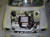
Also, it was to my amazement that the motor was an A+ motor, and it seems it has been fully rebuilt.....

Well I made the guy in possession an offer - and blow me down he took it, as long as I could remove it by the weekend (thanks a bunch to JC (who just had a baby) and to Tony for their help here!!). I said 'hell yes' , as I only paid
$200 for the whole kit and caboodle!!
Good things come to those who wait, and I am glad I waited!!
Okay, I guess you are all wondering what am I going to do with this shell..........
This Morris is earmarked for the mid-mount, RWD 3SGTE conversion that I have always wanted to do. Its name will be..................
MiniR2 (because the engine will be out of an MR2, but you knew that!)
Okay, enough of that.
I would like to digress here for a moment and look at another area of fabrication of the Mini, and come back to the boot later. The reason for this is lately I have had a bit of feedback regarding this area and some folks out in Conversion Mini Land would like to get some information - I am talking about installing the Starlet steering column into the Mini.
As with any project where you take a part of one car and make it fit into another, it is not undertaken lightly, and the steering is no exception. After all, the steering is your major link with the road. It took me a good 2 weekends to get this right - but it was definately worth the effort.
I was not even going to worry about installing the Starlet steering column into the Mini, I thought it was too much hard work, for too little effort - the Law of Diminishing Returns if you like (I had even bought a lowering bracket for the Mini column I was so convinced). But JC nagged me like a bitch that he wanted the Starlet column in 'Hefty', so I reluctantly agreed to have a serious look at how to do this. I decided to experiment on 'The Cat' first, and have all the mistakes, processes and procedures down pat before tackling 'Hefty'.
Lets take a look at what we have originally. The mini column comes up out of the floor at an oblique angle because it is a one-piece shaft. It has to dodge around the pedals and pedal box and then arrive at the driver. It is not central to the driver position, but as you all know, offset to the passenger side. The wheel is inlined at about 35 degrees in the vertical, and about 7 degrees in the horizontal - hardly conducive to a good driving position. Also, there are no switchgear within easy reach (save the indicators) like with ergonimically designed Japanese cars, whereby the indicators, wipers, high beam, pass, lights etc are all located on stalks located either side of the steering wheel.
This was a good a reason as any for putting in the Starlet column (and this was JC's prime mover). For me however, the prime mover was to have an efficient and ergonomically satisfying driving position, that integrated the steering wheel, controls, gear changer and pedals into one sweet package.
I started with the problem of the length of the Starlet shaft, it was about 100mm too long for our needs, even with the splined sliding shaft all the way in. So, first step is to dissasemble the entire shaft. This is done quite easily by removing the circlip at the front of the shaft, at the steering wheel end of the outer tube collar. Next, mark where the outer tube comes to on the inner shaft at the bottom end of the tube, this is where we will cut the shaft and shorten it. Then
gently tap the inner shaft while holding the outer tube with a rubber mallet - its should just slide out of the bottom of the outer tube (hold onto the inner shaft as well as it can pop out suddenly). Next, cut the top uni joint off at at the point it is welded to the shaft. Next, cut the shaft at the mark, plus say 10-15mm (towards where the uni join was), on the column. Join uni joint to newly cut-down shaft. It is imperative that your cuts are perfectly square here and that you weld on the uni joint with good, penetrating welds, without too much heat. Reasemble the shaft.
Do not cut and weld the shaft with out dissasembling it first - there are nylon bearings on the outer tube that the inner shaft rotates on, and the shear pins (its a collapsible shaft) are nylon as well - you will melt or severely damamge these if you welded the inner shaft while it is assembled with the outer tube!!
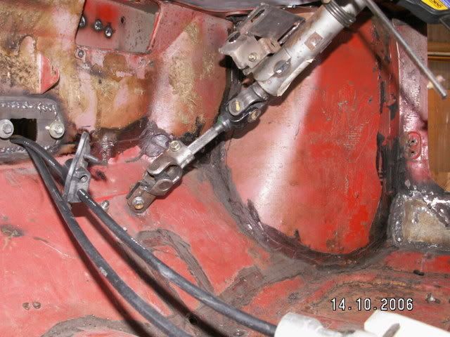
The second problem was how to graft on the Starlet steering knucle joint onto the Mini steering rack spline. There was about 5mm difference in diameters between the two. Upon closer inspection, I found that the Staret knuckle, was a folded piece of metal bent over to form a U-shape on either side. I proceeded to cut off one half of the U on either side with the fine blade angle grinder. Once this was done, I then made some cuts aling the length of the knuckle to allow the two sides of the knuckle to now squeeze together to close up the diameter. It worked a treat!!! The knuckle now clamps on the mini spline like it was made for it. I then welded up where I have cut the knuckle.
In this photo you can see where I have sliced off the bent over wing on the bottom knuckle. Compare it to the knuckle above (where the splined shaft comes into it - see the difference!)
The next job, was to align the column with the exact centre of the drivers position, so it was in the exact centre of the driving position and not necessarily the drivers space. This was no easy feat. I was now constricted by the following:
a) The angle of the knuckle joints could only articulate so far before binding
b) The height of the steering column
c) The interference with the pedals and pedal box
d) The interference with the drivers knees when seated
e) The angle of the steering wheel
f) the method of attachment
g) the interference with the lower dash bar.
Thats a lot of stuff to compromise. I started by finding out what was the exact centre of the drivers position. Was it the exact centre of the footwell?? In fact they were farily close. My measuremenst showed the centre of the drivers position was actually slightly to the outside of the footwell centre line. With this establised, I transferred the drivers centre line up to the dash bar using a spirit level. I then lenghtened that line until it was running along the footwell and on the underside of the dash.
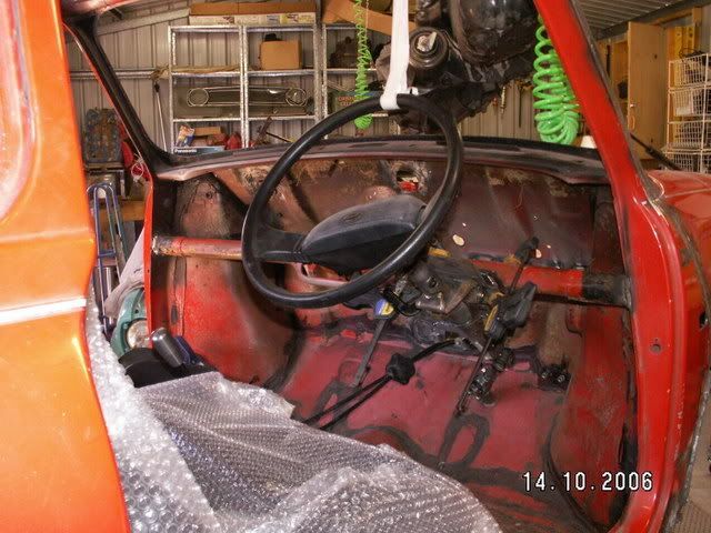
This gave me the centreline that I needed to align the column. If the column for its entire length was plumb with this line, then it would be central to the drivers position. I then clamped the column in place for a test fit. The position felt natural, and well centred.
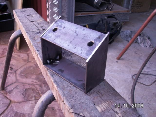
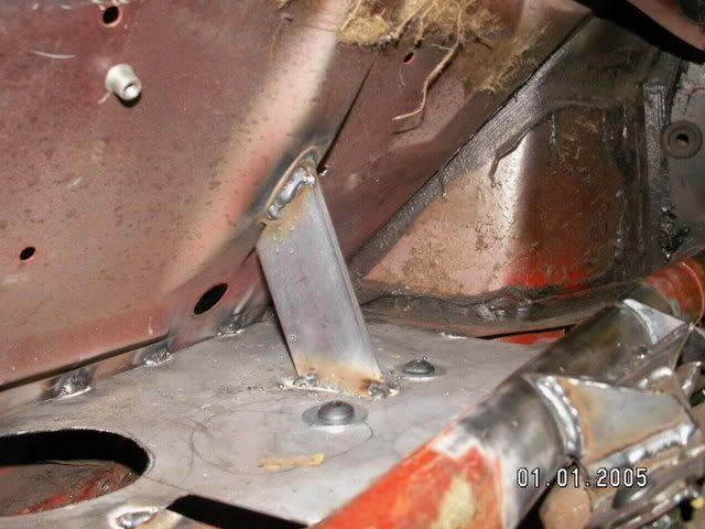
Now, the Starlet column mounts in two positions. Because it has the option of tilting for height, it pivots on the lower mount and slides on the upper mount. We wanted to retain this feature, just for that extra bit of adjustability. A bracket had to be made up for the lower mounting position. This is what the bracket eventually looked like (tacked together ready for welding). It is made out of 3mm plate.
And this is it in position. It is mounted using 2 x 10mm dome head allen bolts (I love them!) with nyloc nuts on the shelf panel, and 2 x nylocs on the column. The second photo shows the finished product after some trimming of the column mount.
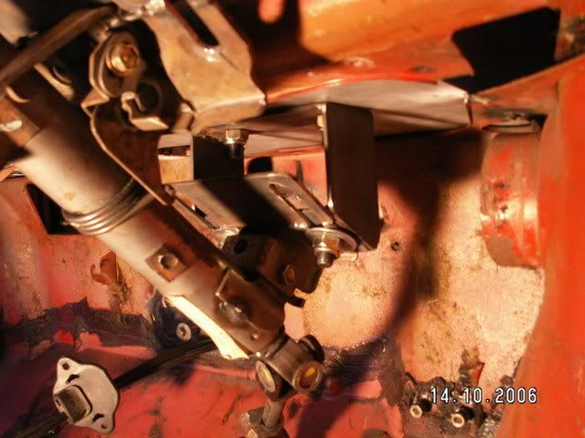
In the above picture, you can see where the uni joint had been welded back onto the cut down shaft, immediately after the end of the outer tube.
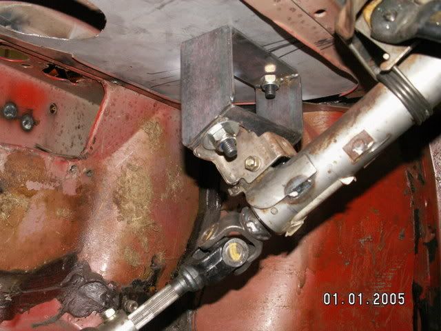
Ok, bottom bracket in place. Now for the top bracket. Because of the position of lower dash bar, a somewhat elaborate mounting bracket had to be devised. This would consist of a flat plate for the column to bolt to (making this ws a PITA, as it had to follow the contours of the column mounting plate!), them some vertical 'buttresses' that would add lateral stability to the bracket. This is what I came up with, and works just great.
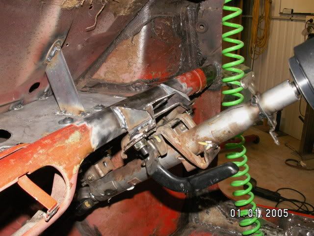
Perfect, except for one thing. Because the column was so solidly mounted at the front, and not so solidly mounted at the rear (after all, its only mounted to 1.2mm sheet steel), it would pivot slightly around the axis of the front mount, not badly, but enough to be annoying. To remedy this, I welded in a short piece of plate that attached from the shelf to the firewall - 'move now you bastard!!!' It cant! And the column is as solidly mounted as the original Mini one would have been. Here is a photo of the transverse brace.
So that was job well done. The top mount will be covered by extending the steering column upper and lower cowling further back down the shaft to hide it. The lower mount will be just painted black, besides you would have to have your head near to the footwell floor to see it anyway. Now, the only drawback to mounting the Starlet column like this is: the lower steering knuckle fouls the brake pedal. This is easily overcome by putting a slight bend ( a set) in the peddle. Its not much, but if you can do it in a press it would be that much easier. I am yet to do mine, but I will post some pics of how much to bend it, and compare it with a standard unbent brake pedal lever.
Now you have a nice central column, with about 25 degrees tilt instead of 35 degrees, with zero horizontal deviation, and with all the switchgear at your fingertips and adjustable for height as well.
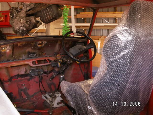
One last photo I want to leave you with.
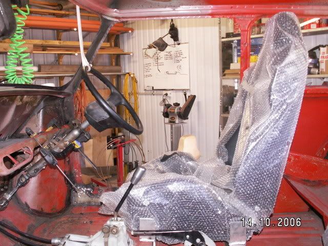
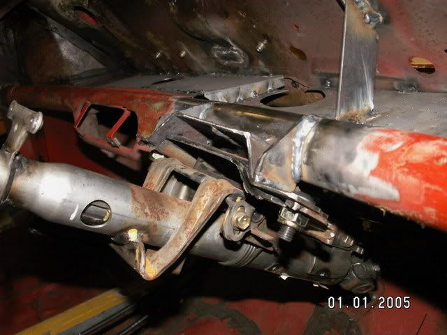
When we were setting up the drivers position, we had three independant people (myself, JC and Tony) judge what was the best position for the steering wheel, seat and shift lever. The only deviation from the three test pliots was the seat reach position (backwards or forwards). If you take a look at the following photo, you will see I have mounted the gearshift lever right back, so the last two mounting holes are actually on the cross tunnel. To do this I had to cut off the handbrake lever mount and weld it back on 50mm further back. But the result, is that you have a perfect seating position, that is: arms bent at 80-90 degrees, knees bent at 10-15 degrees, and the gearshift lever and handbrake fall perfectly to hand.
Next chapter - we give the boot, the boot (Pt II)!


