ausmini
https://www.ausmini.com/forums/

Madmorrie's 4EFTE Morris 1100 conversion
https://www.ausmini.com/forums/viewtopic.php?f=23&t=22593
Page 13 of 24

Author:  madmorrie [ Fri Oct 09, 2009 8:45 pm ]
Post subject: 

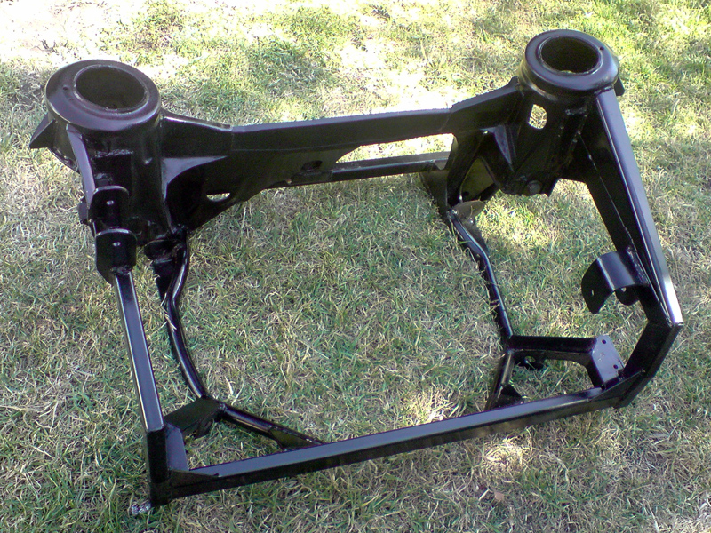
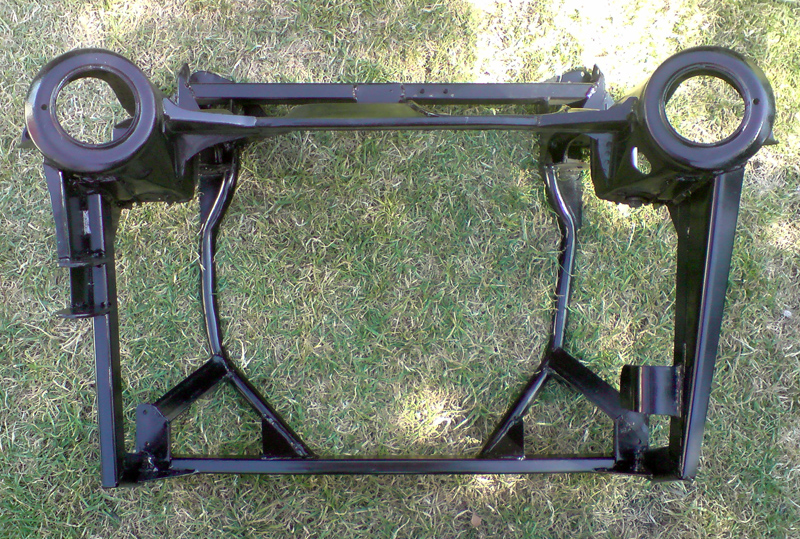
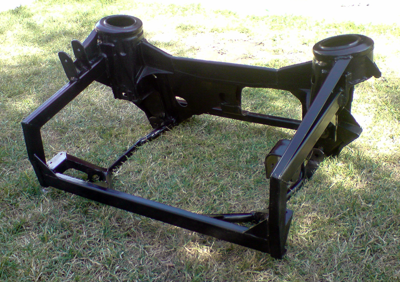
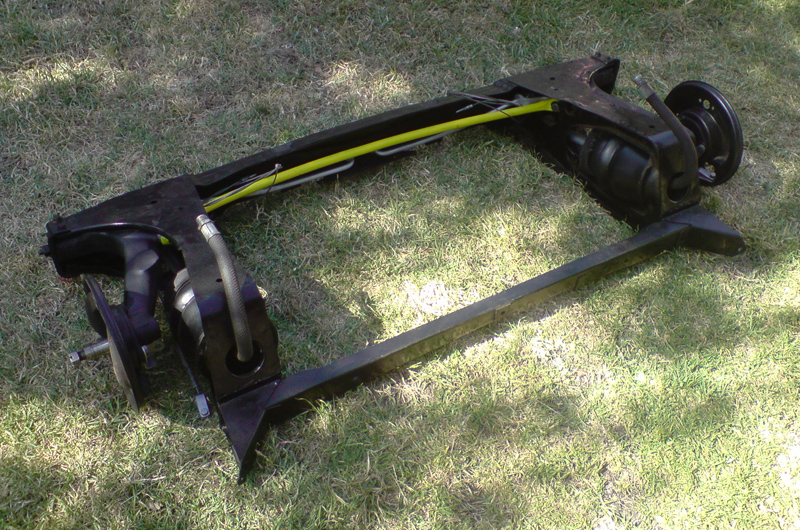
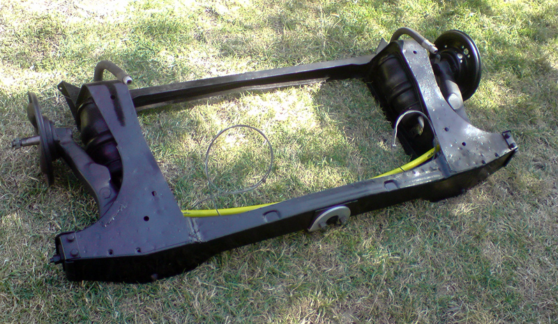
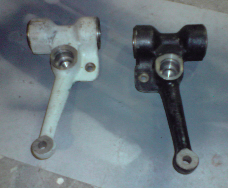
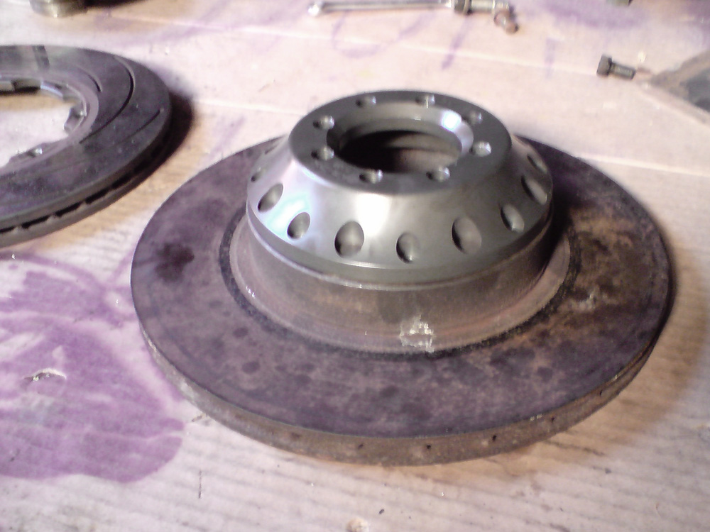
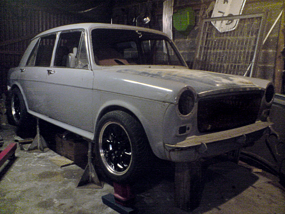
Right, have finally decided what to do for camber adjustment. Thanks to Mr Rosenthal for suggesting I revisit adjusting the top arm. The top arm pivot holes are a much easier proposition to make adjustable due to them being the same size to begin with, much easier to access and the design of the top arm pivot having a built in crush tube (well it's not but it will act as one). After assembling with some mock up tyres (how tough does this look!!) I deemed there to be enough clearance to the inner guard to go ahead. There is no clearance to the outer guard, but some big flares will fix that, I will also run a smaller tyre than this which will help.

Image

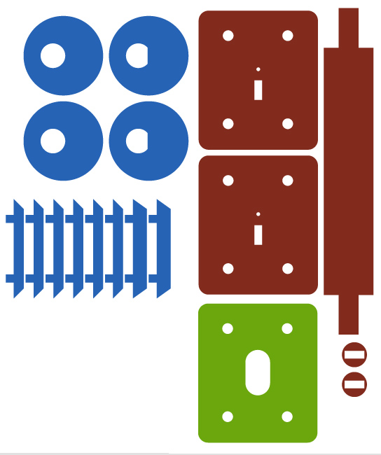
I drew up the desired eccentric washers in Illustrator (and my brother fixed them up in autocad) and have sent them to the waterjet cutters. Hopefully will have a kit of bits next week to finally finish the frame. I figured if I was getting them cu thten I had total freedom so I'd get everything I needed in one hit. You will see the blue washers which will go either end of the bolt. Welded near the head end and flat milled on bolt at the other end. The blue bridge bits will be the blocks either side that the washer push against to move the pivot bolt sideways. The brown bits are the kit to locate the drill guides so i can drill accurate holes for slotting and the bridge bits to go into. The green bit is a guide to file out the slots all the same. Hopefully it works, will post pics of the bits when I get them next week.

Image

Cheers
Madmorrie

Author:  david rosenthal [ Fri Oct 09, 2009 11:58 pm ]
Post subject: 

I do not know how you sub -frame looks like at the top arm mount but this is how I do the mini.
1 bore the rear 1/2" hole in the back of thesub frame out to the same diameter as the front. I use a hole saw with a guide bar.
2 machine up two washers with a step to fit the hole and a shoulder about 1/2" wider [on radius ie 1"dia] The step thickness allows the washer to clamp onto the ends of the top arm pin and subframe as per front original.
3 drill a 1/2" hole off center so it almost lines up with the step section.
4 assemble the whole thing . To adjust camber,leave rear one tight and slack off the front nut. the whole pin/rear washer can be turned with spanner on the back. Once angle is set, tighten up the front.
The whole lot can not move when it is tight. The top arm will pivot on the brgs and the pin does not move, unless it siezes up.
for degree indexing I drill some 1/4" hole to line up with the original oval bracket holes
I have found that with a car on a wheel alignment hoist the rear bolts/nuts are easy to get at from underneath

Author:  madmorrie [ Wed Dec 02, 2009 11:17 pm ]
Post subject: 

Once again I have been slack in updating this thread, for once though I have not been slack in the work department.
I'll do a big update to show everything else in a few days but for now, here is tonights effort, finishing the fuel tank.

Image

Image

Image

Brazed the new top onto my fuel tank. Tank now takes a nissan pump and sender assembly (shortened silvia one but pump is readily upgradable) with an intank surge pot I made and fitted to the tank before I put this top on. Will take a pic of the new shorter pump and the surge pot when I get a chance.

Now just need to test for leaks, splash some paint and replace the hoses and this baby is done. Must remember to add an access hole/clearance panel in the boot floor.

Cheers
Madmorrie

Author:  MiniMan_Alis [ Thu Dec 03, 2009 7:39 am ]
Post subject: 

sounds good but the ppictuures dont workieee

Author:  madmorrie [ Sun Jan 31, 2010 9:14 am ]
Post subject: 

I have been busy lately,

I have now finished the subframe and painted it, rear subby has new bearings, paint and reassembled too. All suspension components and engine mounts etc have been given a coat of paint.

Fuel tank is finished and painted. Steering column mount is nearing completion.

Just going to do a final engine bay mockup and fit everything so I know I've not forgotten anything. Run some brake/clutch lines.

Need to run new fuel lines and replace 1 hydro line.
(Anyone have a spare left 1100 hydro pipe?)

New brakes, half an exhaust and my new 1500 hubs and driveshafts will find there way to me soon. (Thanks guys, you know who you are). All useful and necessary upgrades. Once I have them I should be able to measure for the driveshafts and get them done. And build the back half of my exhaust.

After that I'll chuck it up on my nearly completed rotisserie so I can get under and fix the problem areas. Pretty much just the bodywork, painting and wiring to go.
Oh and some kind of interior.

OK, some pics...

Finished Front subframe
Image

Image

Image

What I found in the rear subframe
Image

Image

Image

New old stock top arms, what are the odds?
Came complete with new bearings and knuckle joints. I love ebay...
Image


Finally, I'm thinking of removing the bumpers, the bumper mounts are rotten underneath so they have to come off anyway, but what do you think of the look?
Image


Cheers
Madmorrie

Author:  toymini76 [ Sun Jan 31, 2010 9:49 am ]
Post subject: 

Hey mate that subframe looks really good, you're going well.
As for the bumperless rear end I say go for it, it seems to really suit it.

Author:  blueminivan [ Sun Jan 31, 2010 10:42 am ]
Post subject: 

I agree. A bumperless rear would look good.
Especially with a nice center mount exhaust.

Author:  74snail [ Sun Jan 31, 2010 11:00 am ]
Post subject: 

Maybe a chrome strip along the bottom edge of the boot lid for a visual relief, and if your going to have a badge about 10cm's in from the bottom right hand corner of the boot at about 30deg
.

Author:  Team Fancy Pants [ Sun Jan 31, 2010 3:08 pm ]
Post subject: 

Subframe looks awsome, Yeh bumperless!

Author:  hallsey [ Sun Jan 31, 2010 6:39 pm ]
Post subject: 

Looks trick MM

Bumperless looks the goods too

Cheers Hallsey

Author:  baby_austin [ Wed Feb 17, 2010 11:33 pm ]
Post subject: 

Hey Mate
Just wanted to say i like your style and that moding an 1100 looks awesome.
With owning a similar car (Austin 1300 Gt) I was wondering if you had time some and could photoshop what you have done with your car (Bumberless shot) but use the Mk2 rear instead ie morris 1300 auto/ 1500 with the sloping taillights instead of the vertical ones. I'm no good at using photoshop and thought it would be interesting to see how it would look with the different tail lights
Thanks
Matthew Austin

Author:  Archangel007 [ Fri Feb 26, 2010 8:16 am ]
Post subject: 

Good work there MM,

I would agree with the bumperless look too, looks very sleek.

I like your progress.

Cheers,
Tricky

Author:  madmorrie [ Wed Mar 10, 2010 8:05 pm ]
Post subject: 

Hi,

Well, since I have lent my car (and therefore it's keys) and can't find the spare set to get into the shed!!! I will do an update. Firstly, here are the pics requested from baby Austin.

Image

Image

Any pics of the 1300 GT would be appreciated, I love them. Start a build thread.

I have a box of goodies arriving tomorrow, all procured via Ausmini in some way. Some bits will look very familiar to you all. Hopefully I can make them all work together to allow me to steer, stop and not break axles...

Axles is just about where I am up to. Once I get the hubs I can mock up the front end and measure up for them. Hoping to get some brake and fuel lines tomorrow too.

Thats about it, will post some pics once I find the shed keys...

Madmorrie

Author:  madmorrie [ Sat Mar 13, 2010 9:11 pm ]
Post subject: 

Well, box of tricks arrived OK. Biggest and most exciting bit was the Tarox brakes I bought from another famous Starlet conversion.

But the &$%#@&% BRAKES WONT FIT!!!!!!!!!

I thought I was chosing the easiest option with a ready made kit, but there is obviously no such thing as an easy option with this car.

They bolt on to the drive flanges just fine, but the calipers foul on the larger diameter 1100 drive flange, which could be machined to clear (maybe 2mm off the outer edge is all it needs) but they will also hit the wheels, and I love those wheels...

Damn.

If I could move the disc and caliper inwards OR go larger diameter, it would clear the wheel centre. Don't want to use spacers if possible. In/out position of the caliper is free as I needed to make brackets anyway.

One possible solution I though of is to replace the tarox disc with a larger diameter one. I had a play with the starlet disc and this is what I came up with.

Image

Image

Image

Image

Would this work? Like structurally?

Madmorrie, back at the drawingboard...

Author:  simon k [ Sat Mar 13, 2010 9:18 pm ]
Post subject: 

madmorrie wrote:
Would this work? Like structurally?


I'm no metallurgist or engineer, but I wouldn't think so. The rotor you've modified is designed to locate on the wheel studs, and is clamped between the drive flange and the wheel, so can't move. You've removed all of that and would be relying on the 8 little screws to holt it in place. That is fine for the Tarox rotors, but the Starlet ones aren't designed for that... I don't think the engineer will like it

just my 2 cents

Page 13 of 24 All times are UTC + 10 hours
Powered by phpBB® Forum Software © phpBB Group
http://www.phpbb.com/