Back to welding...
The last big of subframe strengthening was done - with the subframe bolted on and shell rolled on it's side so nothing warped whilst welding
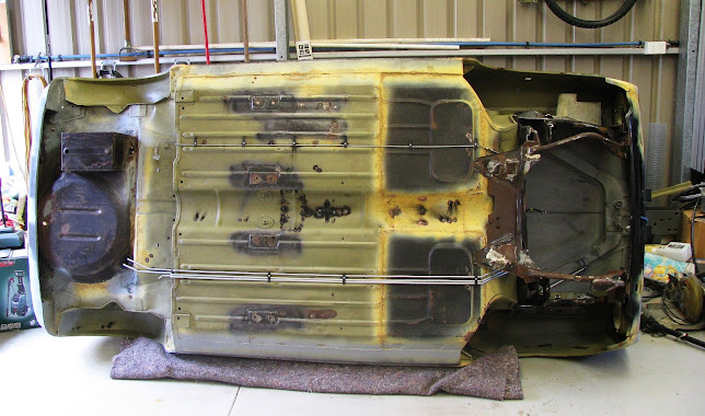
Some additional 1.6mm plates welded over the "subframe "wings. I already have a 3mm plate between the wings for the rear engine mount, and a 25x3mm steel strip welded between the base of the towers. Plenty strong enough


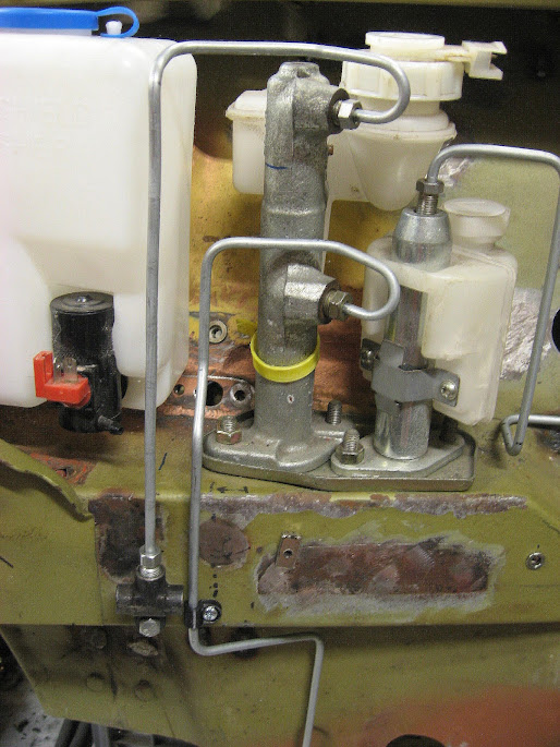
To mitigate any cracking in the toe board (which I've seen in some high powered Minis), I welded on a pair of 2mm thick spreader plates where the subframe bolts through the floor. The nuts were also welded to the plates so there is no need to pull back the carpet if removing the subframe.

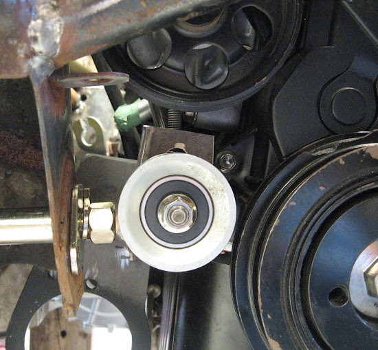
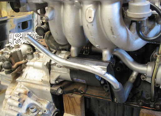
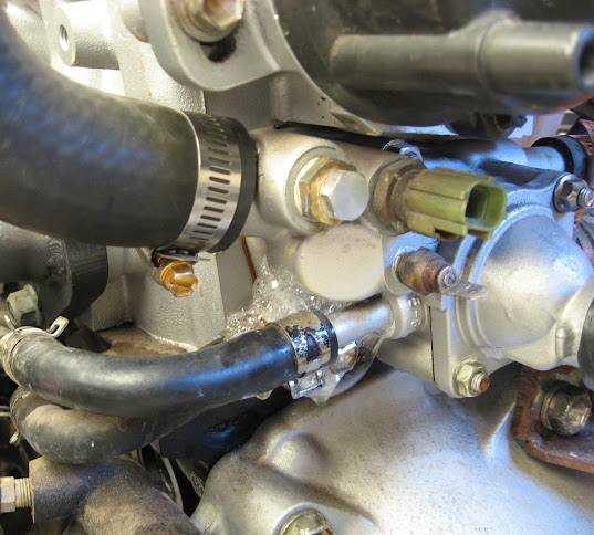
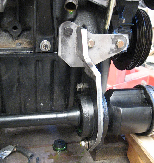
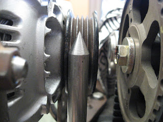
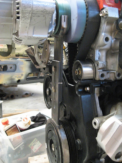
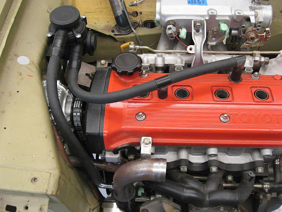
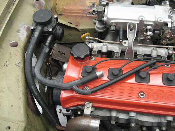
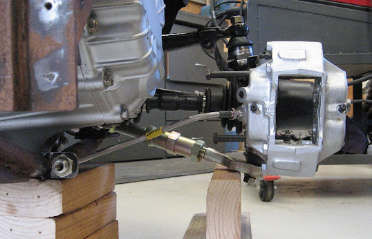
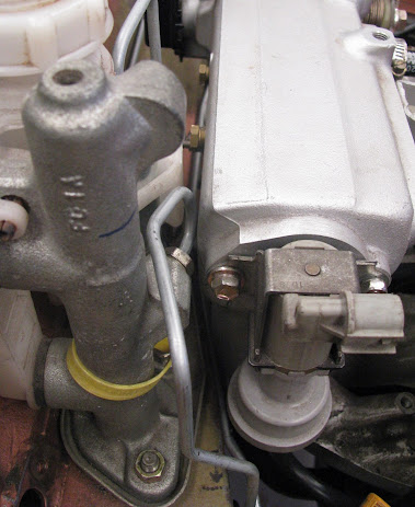
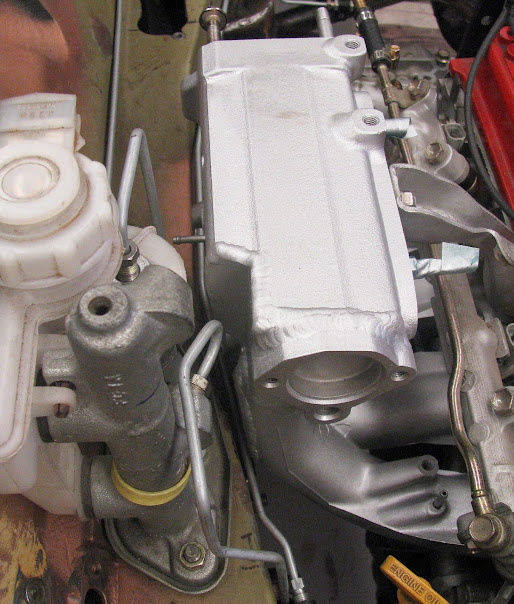
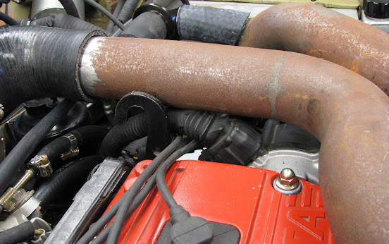
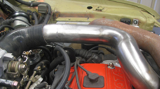
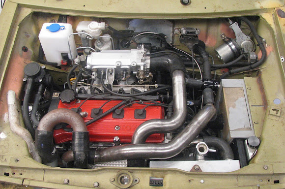
Unfortunately with many Mini engine swaps including this Toyota Starlet 4E-FTE, the engine is so wide that the from subframe suspensions arm pivot shaft cannot be removed as the engine and gearbox block its' removal. On the drivers side, I could remove the water pump and crank pulley to get it out...
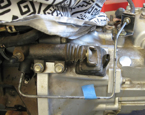
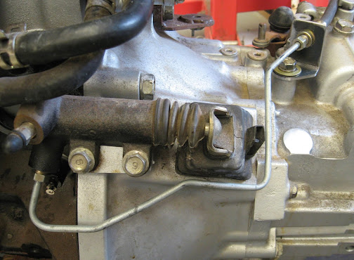
but on the passengers side there's no way to get the pivot shaft out with the gearbox there. Of the dozens and dozens of engine swaps I've seen out there, this is a problem that I've never actually seen solved and I doubt anyone wants to remove an engine just to e.g. replace the rubber seals on either end of the upper suspension arm shaft.
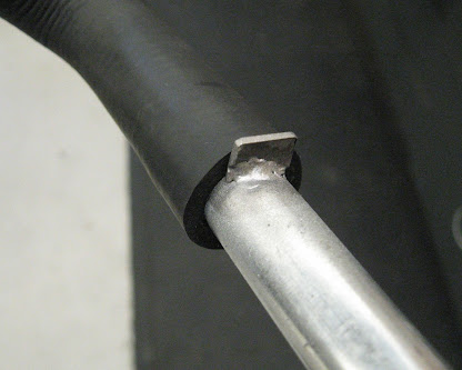
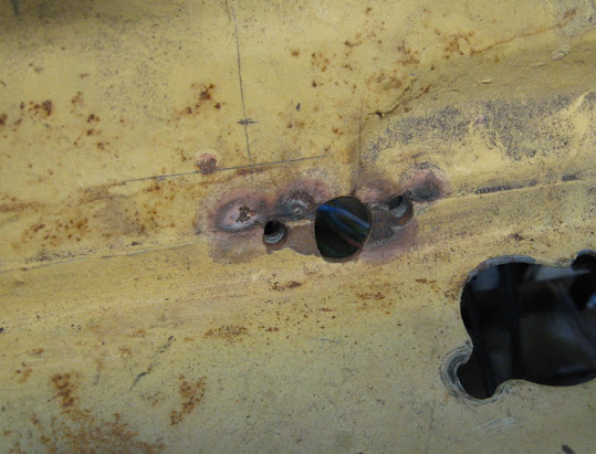
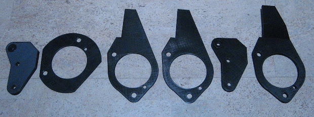
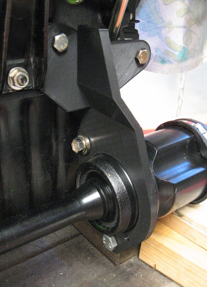
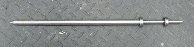
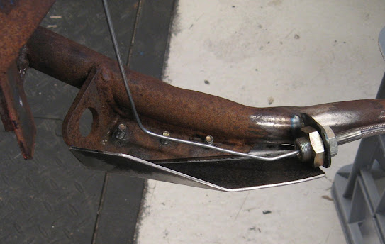
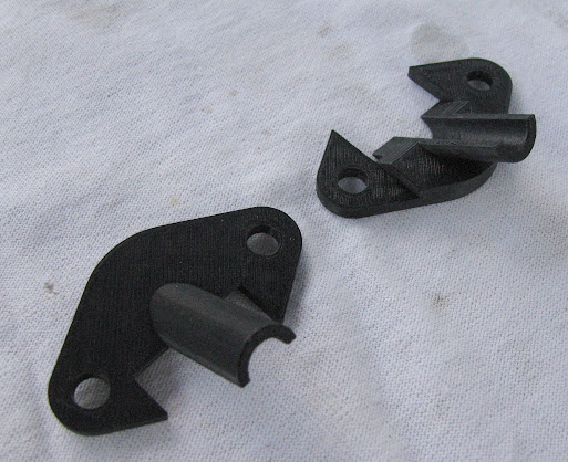
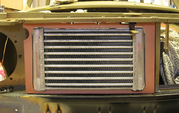
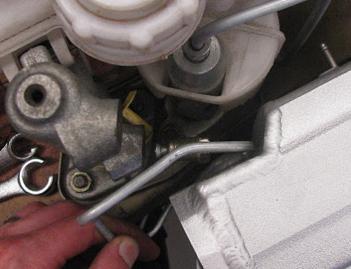
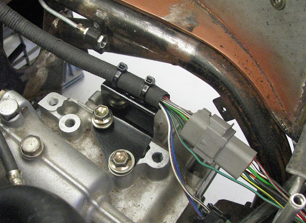
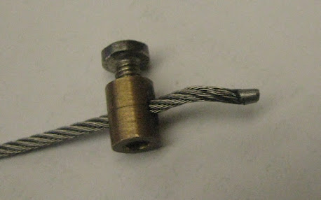
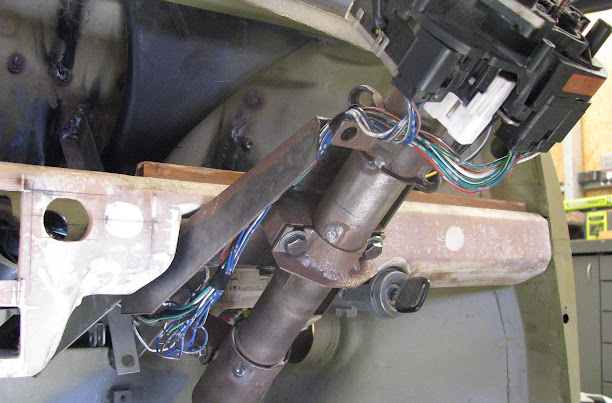
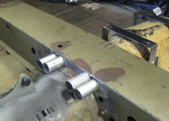
My solution was to modify the subframe to allow the pivot shaft to also be removed rearward. The subframe normally has a 1/2" hole on the rear of the subframe towers for part of the shaft to seat into but this was enlarged
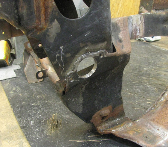
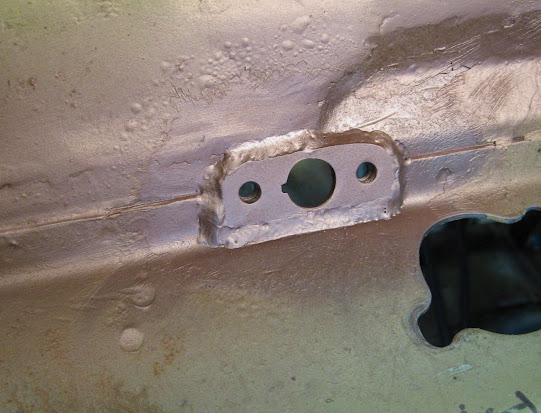
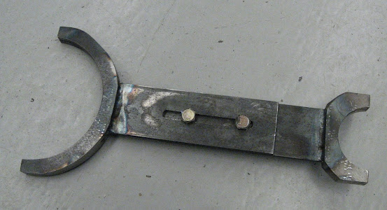
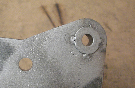
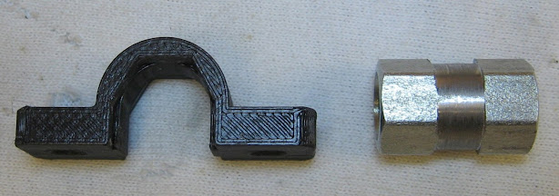
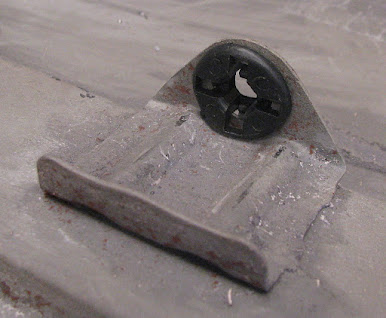
and replaced with a custom locking plate that will replace this 1/2" mount hole. Same size & shape as the factory locking plate piece on the front side of the pivot shaft
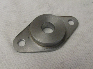
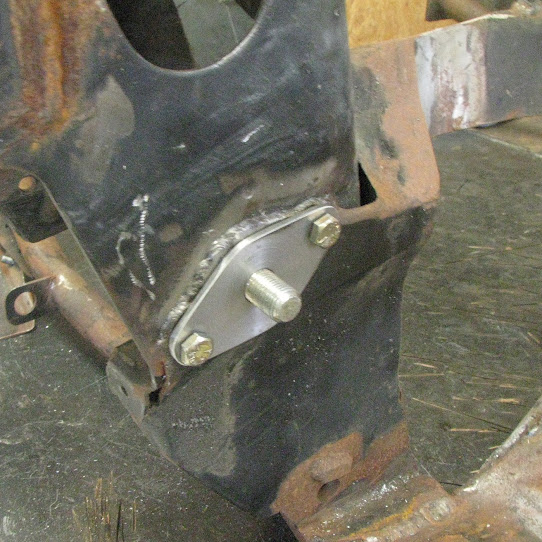
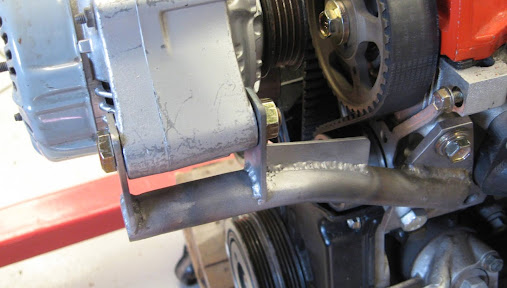
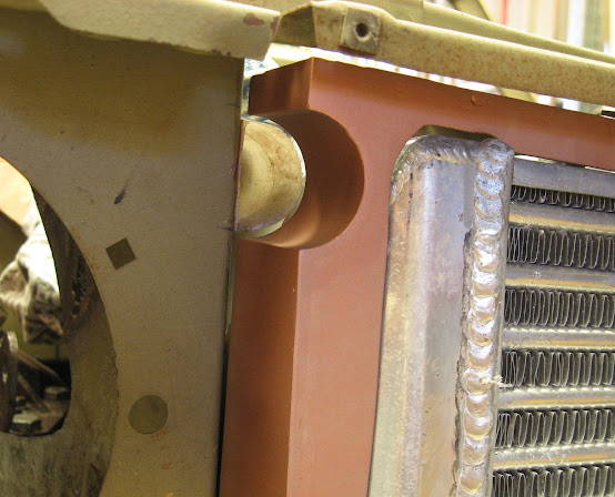
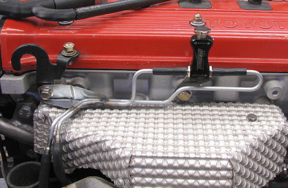
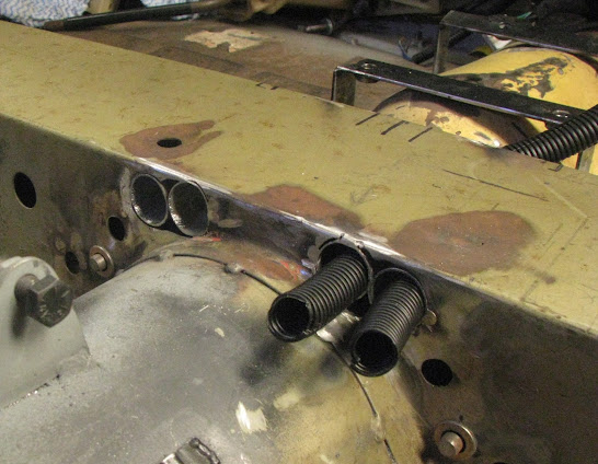
A 1/4" nut was also TIG welded to the inside of the tower for one of the locking plate bolts as this nut would not be accessible once the upper suspension arm is fitted. In this photo you can just see a factory-welded 1/4" nut welded inside the tower on left hand side.

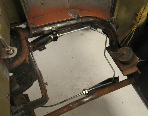
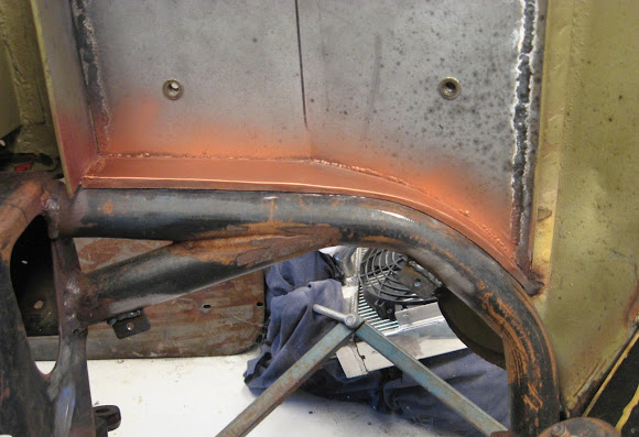
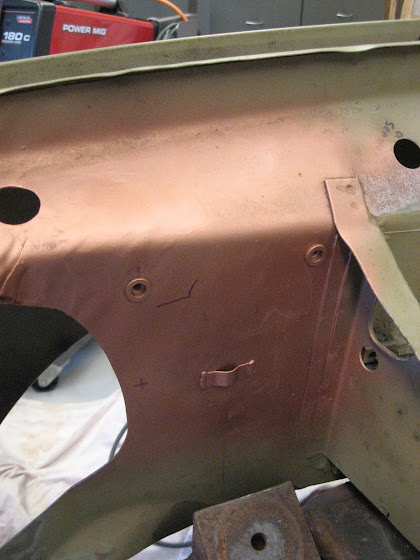
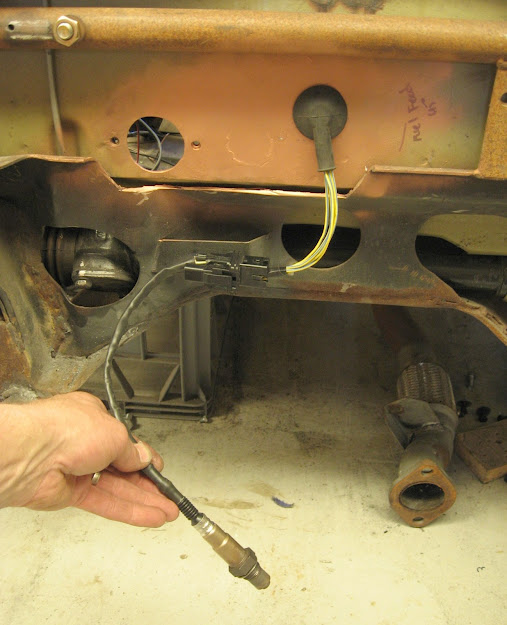
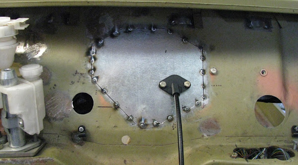
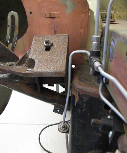
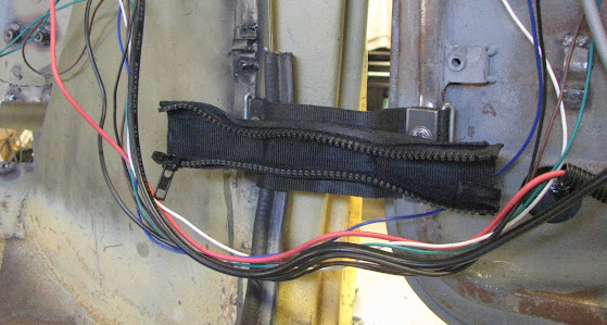
To remove the pivot shaft rearward it required a opening in the upper footwell to access the locking plate bolts and pull the pivot shaft into the cabin footwell area. The drivers footwell (wheel arch adjacent to the opening) :

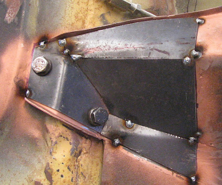
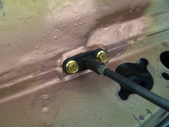
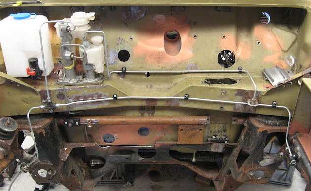
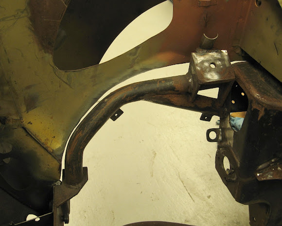
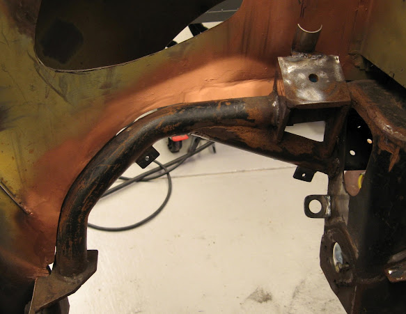
On the shell exterior I welded/formed a perimeter and welded on some nuts/studs.
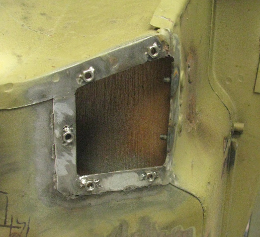
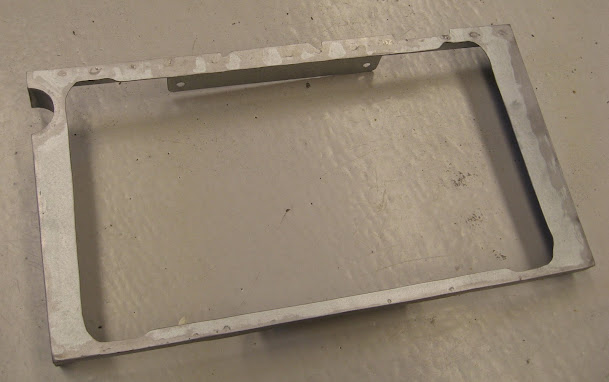
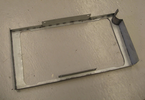
Blanking plates (to be sealed with a custom rubber/neoprene gasket) were then made to close out each opening. The small bump in the plates also provides some additional clearance to the large nut of the end of the pivot shaft (just in case)


_________________
-Alan
I blame my dad for my love of minis. I think I was conceived in the back seat of one

I also blame my Dad for me being 6' 1" - not really the optimum height for driving a Mini.


