ausmini
https://www.ausmini.com/forums/

Mearcat 4E-FTE Clubman Build (Latest update 3-03-24 Pg 28)
https://www.ausmini.com/forums/viewtopic.php?f=23&t=60133
Page 25 of 28

Author:  Mearcat [ Thu Mar 11, 2021 9:30 am ]
Post subject: 

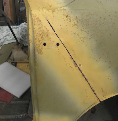
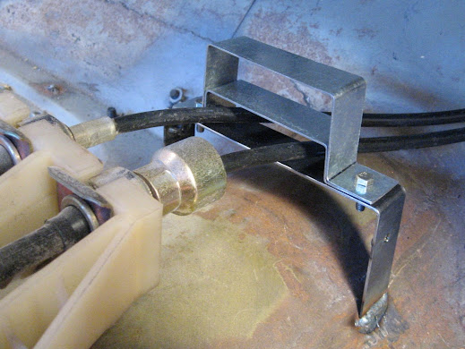
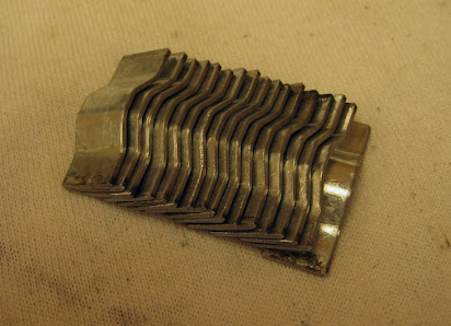
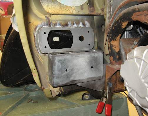
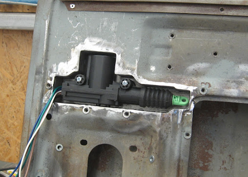
I decided to add to my To-Do list the feature of power door locks / central locking to the Mini and purchased a master and a slave actuator from my Jaycar. The actuators aren't large, but it was going to be a challenge to fit them in the Mini doors and keep them easily accessible in case they need to be replaced. I made an enclosure to house the actuator, made from a single backing plate and some hand bent pieces to create the sides, which were then welded together and then welded into the inner door skin just below the interior door handle.
Image

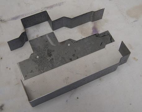
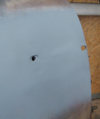
Note the larger hole to maintain access to the door hinge nut!
Image

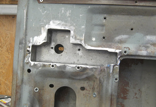
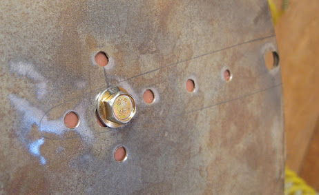
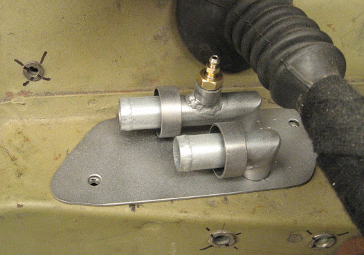
The enclosure has two captive M4 nuts for mounting the actuator
Image

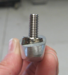
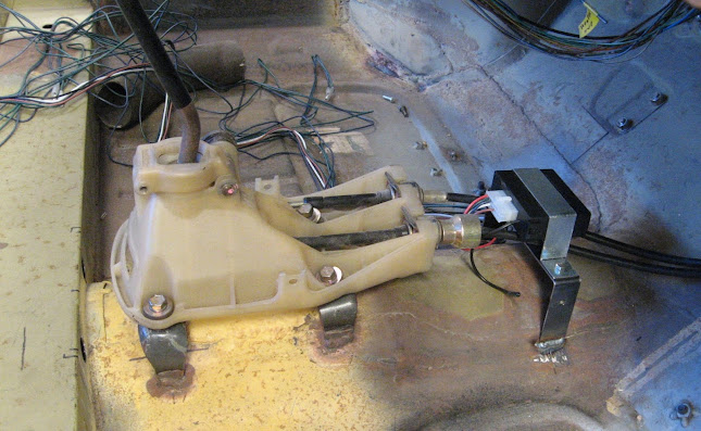
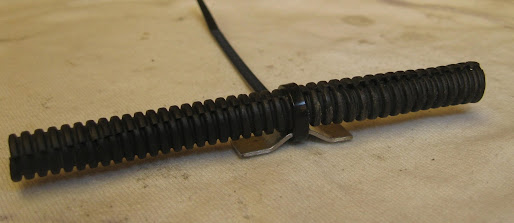
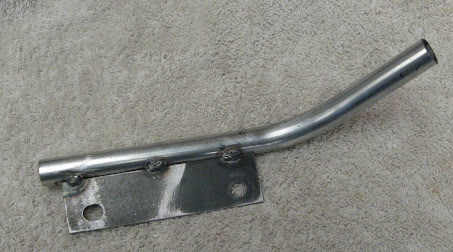
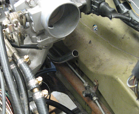
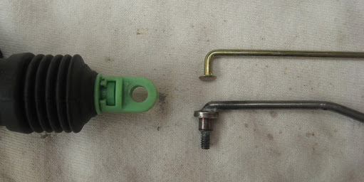
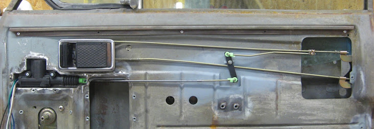
The generic rod that was supplied with the actuators (gold coloured rod in photo below) had a lot of free play within the green clip on the end of the actuator, so I made a replacement rod with a small collar that fits the actuator snugly and will use a nylon lock nut to secure it.
Image

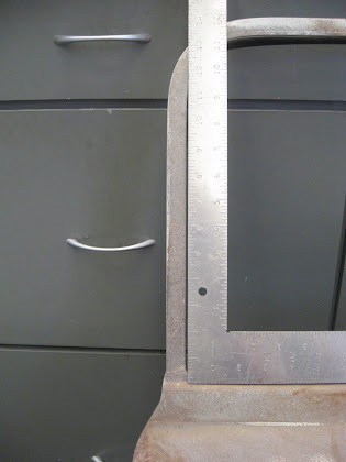
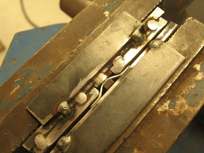
The main issue I faced was that the motion stroke of the actuators is 16mm, but the factory Mini door lock rod only requires approx 8mm to lock/unlock the door. This difference was solved by using a rocker arm with a 16mm movement on one side of the pivot and 8mm on the other side. I machined a standoff for this arm and welded it to the door skin, and also had to create a small recess in the inner door skin for clearance of the rocker arm.
Image

Image

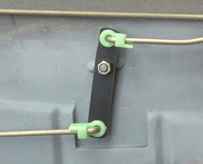
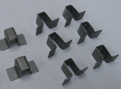
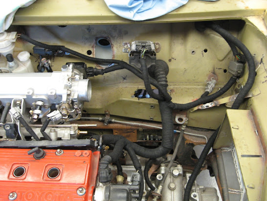
After bending some rods for the mechanism, this was the final layout which easily fits under the custom fibreglass door card.
Image

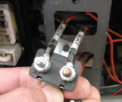
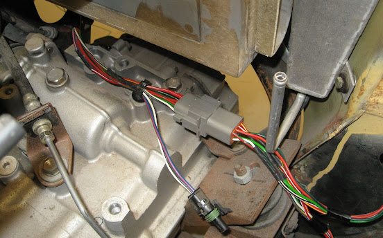
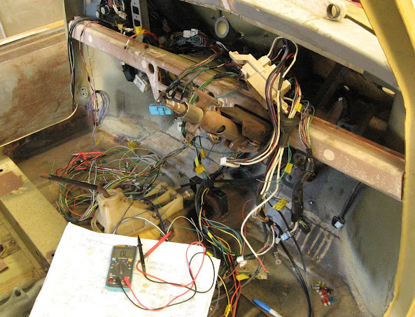
The master & slave actuators have standard wiring (5 wires on master, 2 wires on slave) and I'll be using a central locking controller (with remote keyfobs) to complete the central locking system install. The issue I face now is finding a neat way to route the NINE wires from the doors into the cabin (5x for actuator, 2x for power windows, 2x for speakers)

Author:  winabbey [ Thu Mar 11, 2021 10:01 am ]
Post subject:  Re:

Mearcat wrote:
The issue I face now is finding a neat way to route the NINE wires from the doors into the cabin (5x for actuator, 2x for power windows, 2x for speakers)[/img]

Another superb bit of engineering and fabrication, well done.

Many modern cars have a convoluted soft rubber hose type component to cover and protect the door wiring. Perhaps find a vehicle that has one with enough travel and will concertina sufficiently to squash into the tight space between the Mini door and jamb.

Author:  9YaTaH [ Thu Mar 11, 2021 2:15 pm ]
Post subject:  Re: Mearcat 4E-FTE Clubman Build (Latest update 11-03-21 Pg

Vale Gary Johnston...

https://www.9news.com.au/national/jayca ... 0ca2e285e2

Author:  madmorrie [ Fri Mar 19, 2021 2:23 pm ]
Post subject:  Re: Mearcat 4E-FTE Clubman Build (Latest update 11-03-21 Pg

Nice work Alan,

Fun and games these old cars aren't they?
I've just been doing a the same thing on my 1100 and faced similar problems. Will do an update once I get a moment.

Cheers
Madmorrie

Author:  Mearcat [ Sun May 02, 2021 4:51 am ]
Post subject:  Re: Re:

winabbey wrote:
Many modern cars have a convoluted soft rubber hose type component to cover and protect the door wiring. Perhaps find a vehicle that has one with enough travel and will concertina sufficiently to squash into the tight space between the Mini door and jamb.

I've hung the doors and measured the gap and it's 7mm. Nothing will squash down to 7mm... unless I create a recess in the door for a rubber loom.

Author:  madmorrie [ Mon May 17, 2021 5:53 pm ]
Post subject:  Re: Mearcat 4E-FTE Clubman Build (Latest update 11-03-21 Pg

I had a similar dilemma with my Morris 1100, also I found internal baffles in my doors that were not going to be fun the get wires around/through. In the end I 3D printed a small flat-funnel shaped adapter to go on the end of the supplied rubber tube, fanning out the wires so they have a lower profile to tuck behind the door trim. Then just ran the wires from the end of the dash to the leading edge of the door trim. Not super neat, but it works and made cable runs a ton easier.

Image

Image

Author:  Mearcat [ Sun Jun 13, 2021 10:17 am ]
Post subject: 

A little bit of work on the doors has now been done, although when I first tried to hang them I realised that the guy who did the deseaming work left the panelwork bad enough that the hinges did not sit flush so I had to cut and do little bit of panel beating first
Image

Then when hanging the doors, I found that both doors were not square and needed a little persuasion to get them back :roll:
Before (out of square indicated with a 600mm square)
Image

After
Image

Then I made and welded in some support plates for the upper hinges (plate was welded to the inside of the door) and integrated some fixed angle pieces to get rid of the horrible separate angled washers - which tend to move/rotate when tightened and at worst, distort the panel.
Standard layout with hinges
Image

Improved layout
Image

Support plate welded in via holes in door skin
Image

Once the piece was welded in, the only indication of the plate being there is the hole in the plate behind the outer door skin
Image

Author:  9YaTaH [ Mon Jun 14, 2021 11:51 am ]
Post subject:  Re: Mearcat 4E-FTE Clubman Build (Latest update 13-06-21 Pg

Great work (I hope the door frames are supposed to be square...never thought about that, just about how they sat and their gaps) 8)

Author:  Mearcat [ Mon Jun 14, 2021 9:53 pm ]
Post subject:  Re: Mearcat 4E-FTE Clubman Build (Latest update 13-06-21 Pg

9YaTaH wrote:
Great work (I hope the door frames are supposed to be square...never thought about that, just about how they sat and their gaps) 8)

That's what alerted me to the fact in the first place - the gaps were not even along the B-Pillar

Author:  Mearcat [ Fri Sep 03, 2021 10:14 pm ]
Post subject: 

Cabin wiring! It had to be started at some point. This has taken a few months to get to this...

The cabin fuse box was mounted above the accelerator and with the cabin wiring loom plugged into the power distribution box (glovebox area), then the long task begam to route all the wiring and connectors to their known locations, grouping wires into sections and shortening/lengthening and crimping wires where necessary.
Image

Image

I also extended the rear wiring loom to reach to the boot and all wires that had to be extended were done so with the same colour/trace as the factory wiring. For the rear loom, I added several wires for - power for a boot light, reverse camera power & RCA video cable. The rear loom runs down the centre of the cabin and under the rear seat into the boot. The Mini will be registered as a 2 seater so pinching of any wires underneath the rear seat is not a worry.
Image

I also had to add wiring for my wideband controller and a digital display controller - these were mounted under the drivers seat as they were far too bulky to fit behind the dash. Various sensor bungs had to be fitted too - Inlet air temp just before throttle body, EGT in dump pipe, Wideband O2 sensor in lower dump pipe, Oil Pressure/Temperature in remote oil filter housing, coolant temperature in old A/C sensor port
Image

Then there was the central locking controller which was mounted underneath the centre console.
Image
Image

More new wiring was needed... I used the old A/C circuit/fuse for Cigarette lighter outlet, new USB charging ports in the dash and centre console, digital display & wideband controller. Note that the central locking controller has a constant 12V power supply.
Image

The wiring to/from the 15Amp (auto-reset) circuit breakers for the power windows were labelled.
Image

Author:  Mearcat [ Tue Dec 28, 2021 6:52 pm ]
Post subject: 

A little mote work on wiring... some bigger gauge wiring for grounds - body to intake manifold, and another large gauge (4AWG) cable from body to the engine block (for the starter motor).
Image

A last minute addition was a 8-wire Deutsch (waterproof) connector at the front of the engine bay which will allow me to disconnect all the front lights and indicators from the main loom in a single step. In the case that I need to remove the engine, I will not have to also disconnect the wiring to all the lights/indicators also.
Image

Now that I have all the wiring routes 100% confirmed for the entire car, I made some cable tie mounts to hold the looms around the car. I cut some 30x10mm pieces of 1mm steel and rigged up a quick press jig for my vice. When the vice is closed, it forms a specific shape for the small piece
Image
Image

These mounts will be welded in specific locations and used to cable tie the looms in place
Image

I also made some taller mounts for the cabin/interior. These were welded to the cabin floorpan and will sit slightly proud of the ~14mm of sound deadener, underlay & carpet that I will be installing.
Image

Author:  Mearcat [ Sun Jan 16, 2022 10:13 pm ]
Post subject: 

It's taken a significant amount of time to retrofit all of the Toyota Starlet wiring loom and add any new wiring to the Mini, but it was time to test it all by making my way through my wiring diagram/document and checking off all items - one wire and one fuse at a time. Nothing interesting in terms of photos here, but it took over 20 hours to check everything (continuity) against my wiring diagram and fortunately found no issues in the looms.
Image

Once 12V was attached I went through the same process, now checking 12V available to everything that needed it - and only found a couple of dead globes in the instrument cluster.

With oil in the engine, no ECU/ignition connected I test cranked the engine, only to find the starter motor wasn't working but fortunately this was a simple case of loose connection at the starter motor and then after another test... it worked! What a milestone to be able to crank the engine for the first time in over 10 years! Next step - connect fuel and ignition system for a test proper.

Author:  Mr Anderson [ Tue Jan 18, 2022 5:56 am ]
Post subject:  Re: Mearcat 4E-FTE Clubman Build (Latest update 16-01-22 Pg

A great milestone to reach, well done!

Author:  Mearcat [ Fri Feb 11, 2022 12:31 am ]
Post subject: 

After the first start I had obvious issues with high and surging idle. The surging idle was an easy fix as there were some vacuum ports in the intake manifold I hadn't plugged up. The high idle ended up being the wax stat under the throttle body - a primitive coolant-fed cold start system which are notoriously unreliable when they get old.
Image

As the vacuum ports normally connect to the A/C, power steering and idle up valve, I decided to remove the wax stat completely as I don't have A/C or P/S. I made a custom blanking plate/gasket with a single port to connect the remaining idle up valve
Image

Image

With everything bolted back and engine warmed up, the idle was set using a photo tachometer pointed at the crank pulley.
Image

Other issues found during the first engine start was an oil leak down the gearbox sandwich plate, and the alternator alignment was well off causing the belt to moving side to side as it tried to jump a groove in the 4PK alternator pulley. It's hard to notice the misalignment by eye however when I placed two steel rulers up against the cam gear and alternator pulley, it was then obvious - by approx 1.5 degrees.
Image

Author:  Mearcat [ Sat Apr 16, 2022 2:19 am ]
Post subject: 

So a couple of minor things to sort out before the engine comes out again :

I found that horn mount (behind the radiator) was in the way of the lower radiator hose so I had to relocate the horns to the passenger wheel arch (mounted within an enclosure).
Image

Image

The custom radiator hose adapter needed to be redone to clear the filler neck better so I remade it with an extra bend to clear the radiator filler neck (With some slightly larger pipe)
Old piece :
Image

New piece :
Image

With the engine installed, I found that the coolant hose that runs from the heater core bulkhead adapter to the water pump inlet (between the engine and firewall) had a high chance of rubbing a couple of things so I will make a hard line instead. I used a mock piece to confirm the correct bend angle (which was bolted to the back of the inlet manifold)
Image

Image

I also found that there would be a local high spot in the coolant system above the cabin heater core, which ideally needs a bleed valve for bleeding off air pockets. I remade the heater hose adapter in the bulkhead (that connects the cabin heater core to the coolant system) include a 10x1.0mm threaded bung to screw in the bleeder adapter
Image

With the fuel lines, brake lines, wiring loom, brake booster, carbon canister, heater hoses and intake piping squeezed into one area of the engine bay, the bulky VH44 brake booster ended up causing far too many clearance issues so I decided to forgo the use of a booster and remove it. The engine wiring was then covered in split loom tubing and wrapped in Tesa tape
Image

Page 25 of 28 All times are UTC + 10 hours
Powered by phpBB® Forum Software © phpBB Group
http://www.phpbb.com/