Ausmini
It is currently Sat Apr 27, 2024 5:39 pm

All times are UTC + 10 hours


Post new topic Reply to topic  [ 429 posts ]  Go to page Previous  1, 2, 3, 4, 5 ... 29  Next
Author Message
 Post subject:
PostPosted: Fri Mar 09, 2012 9:04 pm 
Offline
1360cc
1360cc
User avatar

Joined: Mon Aug 23, 2004 10:07 pm
Posts: 10650
Location: SE Melbourne
Put all the braces on there you want, it won't get past the biggest issue which is thick RHS connecting to a thin unsupported plate. To fix it properly (actually, no, fixing it properly would involve binning the A series frame altogether, so we'll just say a suggestion to improve it), the RHS would need to come off, the subframe cleaned up, and fully seal welded, then a doubler plate welded to the front. This would need to be about 6mm thick, and wide enough to spread the load into the sides and top of the tower.
The RHS can then be welded back to the doubler plate (full penetration butt weld with reinforcing fillet on top) and two RHS haunches fitted to stabilise the main member back to the plate, one going up/down the other left / right. An additional plate down the side of the tower to carry some load backwould be a good thing too.


Top
 Profile  
 
 Post subject:
PostPosted: Fri Mar 09, 2012 9:48 pm 
Offline
Yay For Hay!
User avatar

Joined: Wed Sep 08, 2004 9:27 pm
Posts: 15870
Location: Wodonga - Vic/NSW border
just another thought, and you may have already taken care of it, but it looks like the tyres mightn't have a lot of clearance at full lock to those forward spars

Image


Top
 Profile  
 
 Post subject:
PostPosted: Fri Mar 09, 2012 9:54 pm 
Offline
1275cc
1275cc
User avatar

Joined: Fri Oct 01, 2004 4:07 pm
Posts: 4682
Location: sunbury victoria
i was going to weld all the seems up so thats not a worry. would putting a plate over the top of the original metal change much? if its not joined in any way other then a weld around the outside then the bar would be pulling on 3mm plate still wouldnt it? i dont know im not an engineer lol..

yeah i cut the front bits long so i had room to move the side bars so they were straight, il nip the ends off so its flush, and it will clear.


Top
 Profile  
 
 Post subject:
PostPosted: Fri Mar 09, 2012 10:04 pm 
Offline
Yay For Hay!
User avatar

Joined: Wed Sep 08, 2004 9:27 pm
Posts: 15870
Location: Wodonga - Vic/NSW border
meeni wrote:
i was going to weld all the seems up so thats not a worry. would putting a plate over the top of the original metal change much? if its not joined in any way other then a weld around the outside then the bar would be pulling on 3mm plate still wouldnt it? i dont know im not an engineer lol..


I don't think it's enough - that's why I said go back and look at Nigel's approach. Hanging it off the front of the tower isn't the right way to do it

and as for subframes that have broken, I've never seen photos of the damage, if there are any, but does this look familiar?

Image

Image


Top
 Profile  
 
 Post subject:
PostPosted: Fri Mar 09, 2012 10:08 pm 
Offline
1275cc
1275cc
User avatar

Joined: Fri Oct 01, 2004 4:07 pm
Posts: 4682
Location: sunbury victoria
does that have any underside bracing? i dont like how that hard mounts to the gearbox..


Top
 Profile  
 
 Post subject:
PostPosted: Fri Mar 09, 2012 10:10 pm 
Offline
1360cc
1360cc
User avatar

Joined: Mon Aug 23, 2004 10:07 pm
Posts: 10650
Location: SE Melbourne
The extra plate over the old has a function. Being thick it wouldn't deform as much as the thin subframe steel, and you want the weld around the outside to spread the load into the surrounding area.

Think of it like this, if you put a piece of cardboard on a coke can and stood on it, you'll crush the can. Replace the cardboard with MDF and you'll still crush the can.

Now, get 20 cans and arrange them in a square, and put the thin card on and stand on it. The card will sink in the middle, the cans may be damaged as a result.

See where this is going? With everything combined it'll work as a unit, so the MDF on the cans won't crush because your weight would be dispersed throught the thick mdf into a greater spread area of multiple cans.


Top
 Profile  
 
 Post subject:
PostPosted: Fri Mar 09, 2012 10:23 pm 
Offline
1275cc
1275cc
User avatar

Joined: Fri Oct 01, 2004 4:07 pm
Posts: 4682
Location: sunbury victoria
thats true, with the cutout for the rubber cone theres very limited area to put something sufficient.. will have to have a think..

ps, is that baracades frame? if that cracked was it due partly to the massive power/solid engine mounting? i know that it would have something to do with the weakness of the frame too but if im running half the power if that, and rubber mounted, would it be putting quite as much stress on that?


Top
 Profile  
 
 Post subject:
PostPosted: Fri Mar 09, 2012 10:41 pm 
Offline
Yay For Hay!
User avatar

Joined: Wed Sep 08, 2004 9:27 pm
Posts: 15870
Location: Wodonga - Vic/NSW border
meeni wrote:
if that cracked was it due partly to the massive power/solid engine mounting?


remember I said at least two? the other one I know of was rubber mounted, and didn't make nearly as much power

like I said, I reckon it's just a crap design...


Top
 Profile  
 
 Post subject:
PostPosted: Sat Mar 10, 2012 2:21 am 
Offline
1275cc
1275cc
User avatar

Joined: Sat Nov 19, 2005 1:37 pm
Posts: 2495
Location: Vegus, Brisvegus
Good on you Simon for making the hard call on this. It is too easy to just keep quiet on these.

The engine has to be held up and the factory did this with a beam that runs from footwell to trailing link mount Under the engine. The beam tapers along its length and has strengthened cut outs for the drive shafts. Under the engine the beam has a Z section with a certain moment of area. I reckon the best subframe designs continue with that design and modify that beam to go under and around the gearbox. If the original moment of area is exceeded you should be good with your engineer. There should be no sudden changes in section stiffness as these lead to cracking so tapered gussets should be used at every section change.

Hold the engine up from underneath in the centre and react the torque separately with a member attached to the engine and running under the floor to the seat cross member.

NG's swift mini has exactly the type of subframe I describe but without the good torque reaction system. It is by far better than top-slung designs.

If there is no alternative to mounting off those towers add 3mm thick tapered gussets to the outside surfaces AND make sure you have decent compression members under the engine from trailing link mount to rear of the drive shaft holes. These can't be too bendy going in all different directions.

M


Top
 Profile  
 
 Post subject:
PostPosted: Sat Mar 10, 2012 8:28 am 
Offline
religious status
religious status
User avatar

Joined: Fri Mar 19, 2004 6:19 pm
Posts: 39643
Location: near Baulkham Hills, NSW
I hate how many 4EFTE conversions have NO bracing at all under the engine to support the RH tiebar mount. (LH side is OK).
Under acceleration, on the RH side you are putting 1/2 your 200?HP worth of forward thrust into a flimsy bit of RHS tube dropped down from above. Gusseted above or not, it ain't good enough.
Baracade's frame flexed so bad, it cracked the RH guard.
I know of 2 others that followed this design, it's not good.

If there was no other way due to clearance I would weld a 2" tube through the sump and bolt a tie bar in there.

_________________
DrMini- 1970 wasaMatic 1360, Mk1S crank, 86.6HP (ATW) =~125 @ crank, 45 Dellorto (38 chokes), RE282 sprint cam, 1.5 rockers, 11.0:1 C/R. :mrgreen:


Top
 Profile  
 
 Post subject:
PostPosted: Sat Mar 10, 2012 1:20 pm 
Offline
1098cc
1098cc
User avatar

Joined: Wed Oct 01, 2008 11:14 am
Posts: 1906
Location: Brisbane Qld, North side
not sure if con or hard brothers did my subframe but golly it is done well & thick bracing.

never had it crack or anything.


Top
 Profile  
 
 Post subject:
PostPosted: Sat Mar 10, 2012 1:59 pm 
Offline
Bimmer Twinky
User avatar

Joined: Mon Sep 06, 2004 4:36 pm
Posts: 8606
Location: Brisbane
Con took note of the way we were doing our suzi frame & (sort of) copied it

_________________
No offence intended here but--> anyone writing a book about minis 30 years ago may not have experienced such worn or stuffed-with components as we are finding these days.

You should put your heart & soul into everything you do.


Top
 Profile  
 
 Post subject:
PostPosted: Sat Mar 10, 2012 4:24 pm 
Offline
1275cc
1275cc
User avatar

Joined: Fri Oct 01, 2004 4:07 pm
Posts: 4682
Location: sunbury victoria
Just to confirm, it does have underside bracing and pretty heavy at that, it's not just hanging from that top bar, id be interested to see some other Suzuki frames because every single one ive seen on here and in the uk looks similar to mine. I had a look today at how I could go about fixing something up like that original picture but with standard suspension it doesn't Leave a lot of Room, you also need to cut away a lot of metal around the cross member to make that fit.


Top
 Profile  
 
 Post subject:
PostPosted: Sat Mar 10, 2012 10:24 pm 
Offline
1275cc
1275cc
User avatar

Joined: Sat Nov 19, 2005 1:37 pm
Posts: 2495
Location: Vegus, Brisvegus
A good design shouldn't need to use thick plate or other heavy sections. You'll never see much thicker than 3mm plate on a factory car, even a new 4wd ute. The original subframe uses a mix of 2.5 and 2mm sections (or their imperial equivalent).

The trouble with thick steel sections is they are too stiff for what they are attached to and generally have low moments for their mass.

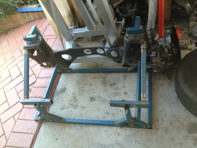
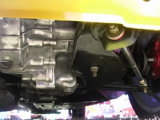
Here are some pics of NG's subframe from a few years ago.

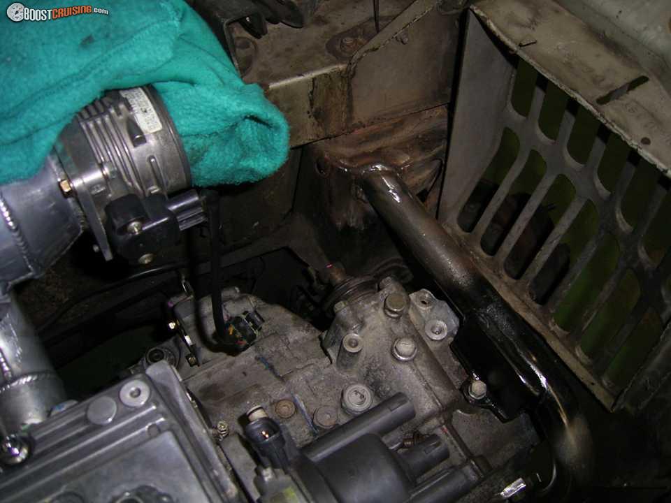
Gearbox side. See how the original section is replaced with a similar Z section that goes around the gearbox and holds up the engine mount. Also note it is continuous under the drive shaft hole all the way back.

Image

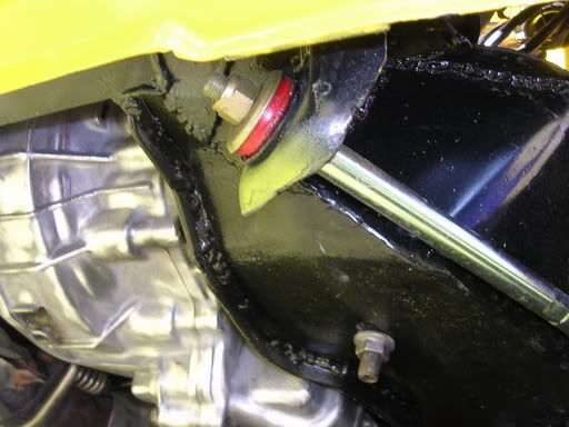
Another view of gearbox side

Image

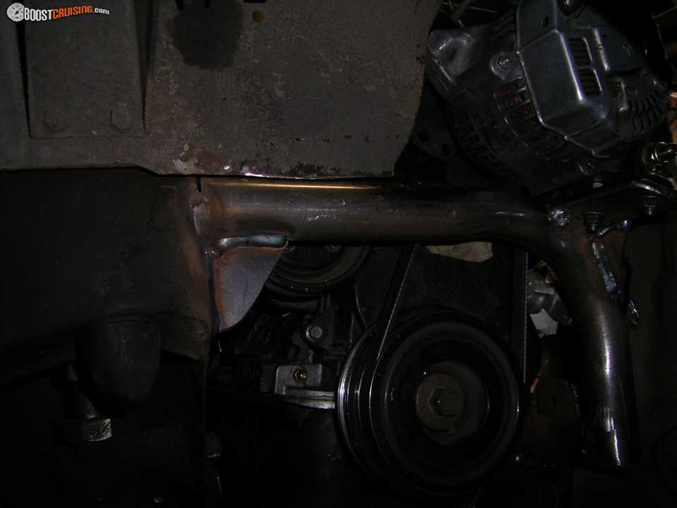
Here is the engine side. Again the engine is held up by a fabricated section.

Image

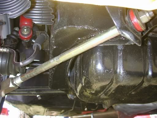
Another view of engine side. It would have been possible to make this section deeper back from where the track rod passes under. You can't see in this pic but the bulge shape is to clear the crank pulley.
Image

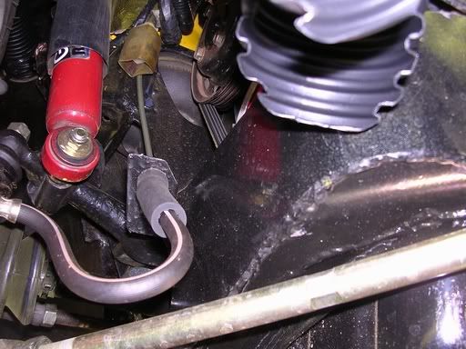
So the above example uses three engine mounts. One under the gearbox and one either side of the engine. There is also a supplimentary torque reaction mount up near the master cylinders but it doesn't add much. I would be tempted to not use the mounts on the side of the engine and have a single on the timing belt side plus a fabricated structure for torque reaction reaching back down the tunnel. That would take the load off the cross element at the front of the subframe.

Some more photos in that photobucket album.

M


Top
 Profile  
 
 Post subject:
PostPosted: Sun Mar 11, 2012 10:07 am 
Offline
Yay For Hay!
User avatar

Joined: Wed Sep 08, 2004 9:27 pm
Posts: 15870
Location: Wodonga - Vic/NSW border
thanks for that Mokesta - I did want to see that frame

the design of the original mini subframe really is brilliant


Top
 Profile  
 
Display posts from previous:  Sort by  
Post new topic Reply to topic  [ 429 posts ]  Go to page Previous  1, 2, 3, 4, 5 ... 29  Next

All times are UTC + 10 hours


Who is online

Users browsing this forum: No registered users and 109 guests


You cannot post new topics in this forum
You cannot reply to topics in this forum
You cannot edit your posts in this forum
You cannot delete your posts in this forum
You cannot post attachments in this forum

Jump to:  

© 2016 Ausmini. All garage work involves equal measures of enthusiasm, ingenuity and a fair degree of irresponsibility.