ausmini https://www.ausmini.com/forums/ |
|
Mini dungers motor + video https://www.ausmini.com/forums/viewtopic.php?f=5&t=40206 |
Page 1 of 3 |
Author: | mini-dunger [ Sun Mar 16, 2008 3:53 am ] |
Post subject: | Mini dungers motor + video |
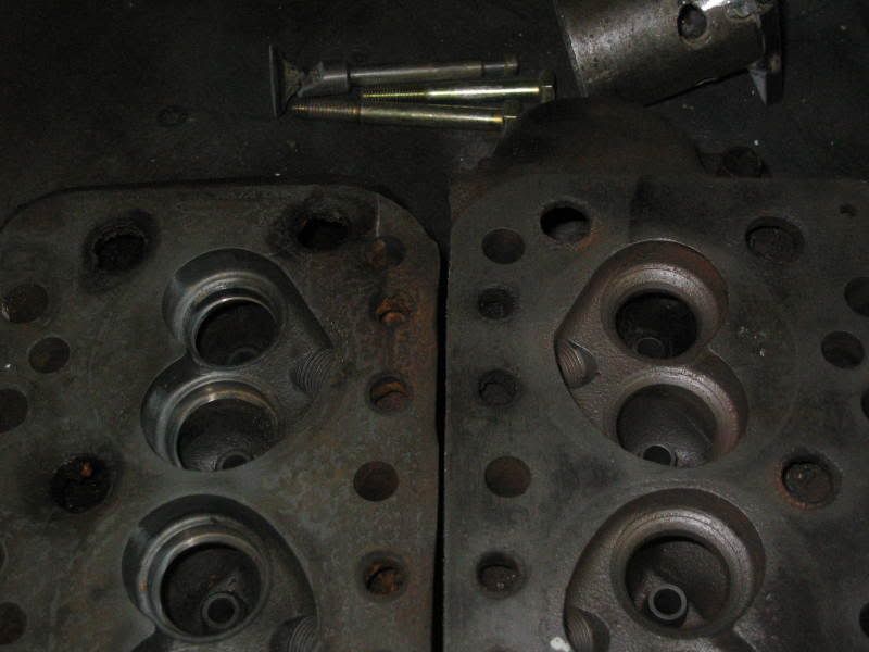
I thought I would just make a little thread about my engine build and some of the stuff I have learnt along the way. Dr mini is a gun. I have never built anything from scratch before and he has thanklessly helped me the whole time. Without his help I would not have gotten far. I had an 1100 at home and I was to tight to pay for an import or buy a rebuildable 1275. Big mistake, honestly the amount of money I have poured into this the $700 bucks for a rebuildable big bore is nothing. I have basically done something to every part of the engine to make it go better appart from wedging the crank (which I now regret). I had work done all over the place so I got to meet some cool guys that got to play with kickass machines and I also met some people I would not look back on fondly. Picks to follow ![]() |
Author: | mini-dunger [ Sun Mar 16, 2008 4:20 am ] |
Post subject: | |
Instead of buying a "good" i did it myself. I had the good doc machine me down some 1100s valves. So basically I just modded the head to suit. I basically did it in 3 stages I had a machine shop bore the first 8 or so mm of the ports 3mm smaller than my valves. ![]() I then put the head on my pedestal drill with a nice tapered burr and did some more blending. ![]() and this is after I blended in the last little bit with a ball shaped burr. ![]() |
Author: | mini-dunger [ Sun Mar 16, 2008 4:36 am ] |
Post subject: | |
While I still had the valve guides in I made this little thing to scribe a radius around the valve.I just drilled two little holes then inlarged on exactly the same size as a valve stem. I stuck a scriber in the little hole and spun it around marking within the gasket only. I measured .780 for the exhaust valves and about 1in for the inlets. This is my practice head. ![]() I brought a cheapy drill with intentions of wrecking it while doing this head but its held up really well. I connected a little vacuum to it and it worked quite well. Later on I grease the bed of the drill up and it worked a treat. ![]() I dont have any photos but I basically ground off the valve guide bosses flush with the port walls. I put a nice radius between the inlet ports and just made it all nice and smooth. I didnt make the ports much bigger than standard really. I am trying to keep it drivable besides the valves only a few mm of the seat most of the time so the ports really are not the restriction. Well not with my little valves they arent. this is it finished. I had 70 thou off it to try and regain some compression. I will go into that later. ![]() |
Author: | 1018cc [ Sun Mar 16, 2008 8:24 am ] |
Post subject: | |
What's the go with the funny chamber shape? Is the good doc trying something different with the heads to get a bit more power? Looking good! <edit> I carn't speel ![]() |
Author: | spraycanmansam [ Sun Mar 16, 2008 9:40 am ] |
Post subject: | |
Looks like he's trying to deshroud the valves as much as possible but also keep the squish. |
Author: | drmini in aust [ Sun Mar 16, 2008 9:54 am ] |
Post subject: | |
The valves : inlets- (new) 33mm Morris 1100S, back cut as per Vizard. exhausts- (new) 29mm Morris 1100S, turned down to 27mm and faced off to restore thickness. |
Author: | mini-dunger [ Sun Mar 16, 2008 6:01 pm ] |
Post subject: | |
1018cc wrote: What's the go with the funny chamber shape?
Is the good doc trying something different with the heads to get a bit more power? Looking good! My main focus was deshrouding the inlet valves because they have to suck pretty hard to fill the chamber where as the exhaust gases basically explode out of the chamber. I ended up with about a 31 cc chamber volume as it was. With .60 over 1098 I needed around 23- 24 cc to get 10-1 compression. I used hypertech pistons and they had a massive dish around 8cc. In order to get some "squish" back I had the machine shop cut .050 of the tops of them. ![]() So I put it together again and used my dial indicator to find 1) any difference in stroke on each piston 2)How much I had to mill of the block As it turns out there was 6 thou difference between no.1 and no.4 So i had to number all the pistons and send them back to the shop for a touch up. I also had them machine 63 thou off the block. This set the pistons 5 tho above the block. After all this I managed to end up with a compression ratio of around 10 - 1. You can see in this picture how much I milled off the head. ![]() |
Author: | 1018cc [ Sun Mar 16, 2008 6:14 pm ] |
Post subject: | |
At least they listened to you and didn't cut the engine number off! 31cc's, those are some big chambers ![]() 10:1 compression should make for nice motor ![]() |
Author: | mini-dunger [ Sun Mar 16, 2008 9:21 pm ] |
Post subject: | |
I sent the block off and had it acid dipped, skimmed, and new cam bearings put in. I forgot to punch out the oil plugs so I had to get it re dipped after I some more machining done. I also rammed a bottle brush in anywhere it would fit. ![]() The oil holes and the gallerys didnt match up so i had to grind the bit I have marked in this photo. ![]() I also had .200 machined off both sides of the big ends on the conrods. I weighed em before I sent them off and there was 16 grams difference. I then ground all the casting dags off and made them all weigh the same. I then had the big ends resized and made sure they were straight. as it turns out they were. I then pressed out the little ends and replaced em. I had to get them bored out so I had em straightened again after the little ends were sorted. I replaced the bolts with socket head capscrews. These rods cost me about $600. I hope they dont break ![]() |
Author: | graham in aus [ Sun Mar 16, 2008 11:29 pm ] |
Post subject: | |
Nice work. BUT! Make absolutely sure there are no sharp edges on the raised part arrowed here! ![]() Sharp edge acts as stress raised, small crack starts and develops.... Ask me how I know. . . . . . . ![]() ![]() ![]() |
Author: | mini-dunger [ Mon Mar 17, 2008 7:07 am ] |
Post subject: | |
drmini in aust wrote: The valves :
inlets- (new) 33mm Morris 1100S, back cut as per Vizard. exhausts- (new) 29mm Morris 1100S, turned down to 27mm and faced off to restore thickness. I forgot to mention, these valves are longer than standard by about 2mm. SO I had to use 4 rocker shaft lock tabs underneith the rocker posts to stop the rockers from fouling the valve springs.. I put offset bushes in my rockers so I needed to enlarge the little hole in the rocker posts and push the hard against the head studs. What this does is bring the rocker pad back nice and level with the valves. Offset bushes are a pain in the ass. They have to have a oil hole drilled in them and then they have to be reamed to fit your new rocker shaft. You also have to press out your old bushes and press these new ones in. That in itself is a real hassle as they only go in one way (basically) and if the most offset part of the bush is in the wrong position the whole thing is a waste of time. Plus It cost me a fortune getting them reamed. The company in the UK I brought them from markets them as 1.5 ratio bushes. This is entirely untrue. Doc made some better ones than I have and they worked out to only a little over 1.3. IMO if you want them get someone like Doc to make em for ya. I made this press out of a jack and some junk I had laying around.I put a couple of old guides in the bench drill and filed em a bit so they dont get stuck when the push the old guides out. I used it to press out and in my valve guides, rocker bushes, little end bushes, and a whole bunch of other stuff. It just sits out of the way mostly but I do use it alot. ![]() these are the pain in the but rocker bushes, not very glamourous really..... ![]() |
Author: | mini-dunger [ Mon Mar 17, 2008 7:09 am ] |
Post subject: | |
graham in aus wrote: Nice work.
BUT! Make absolutely sure there are no sharp edges on the raised part arrowed here! ![]() Sharp edge acts as stress raised, small crack starts and develops.... Ask me how I know. . . . . . . ![]() ![]() ![]() nah theres no edges there Its got a nice radius on em.... No sharp edges anywhere. |
Author: | mini-dunger [ Mon Mar 17, 2008 7:20 am ] |
Post subject: | |
Then next thing I had done was the flywheel. I had .200 machined off the outside and then I had them face the inside where the clutch plate goes. I made sure they dynamically balanced it so it doesnt self destruct and cut off my frank and beans. It really was made from crap steel you can see different textures in the metal. Should be ok though. I had some hard metal washers made up at .200 to go under the straps. ![]() it ended up weighing in at 6.4 kg. Any lighter I think the cam would make it too hard to drive in traffic. Once this was done I sent everything from the harmonic balancer to the clutch in to be balanced. |
Author: | mini-dunger [ Mon Mar 17, 2008 8:50 pm ] |
Post subject: | |
Basically that was it for the internals. I replaced the old head bolts with new studs. I had GR grind me up a re13 so that went in along with some new lifters. Once it was all bolted together I poped a crank dial on with a magnetic stand and indicator on no.1 inlet valve. I found where max lift was and then checked where the crank was in relation to it. It was spot on so I didnt need any offset keys and best of all I wasnt a tooth out. ![]() I had a 4 syncro box rebuilt for it all to sit on. I pulled the rod change selector to bits to find it in good nic with no slop at all. I made a new gasket and pumped it full of grease. The rod change boots are NLA so I scavenged pick apart till I found on that was good. Bolt ons tomorrow ![]() |
Author: | 1018cc [ Tue Mar 18, 2008 9:41 am ] |
Post subject: | |
I love this thread and how fast it is moving ![]() |
Page 1 of 3 | All times are UTC + 10 hours |
Powered by phpBB® Forum Software © phpBB Group http://www.phpbb.com/ |