Ausmini
It is currently Wed Jun 25, 2025 8:28 pm

All times are UTC + 10 hours


Post new topic Reply to topic  [ 17 posts ]  Go to page 1, 2  Next
Author Message
PostPosted: Mon Dec 22, 2014 12:30 pm 
Offline
848cc
848cc
User avatar

Joined: Thu Apr 03, 2014 10:28 am
Posts: 232
Location: Canberra
G'day everyone!
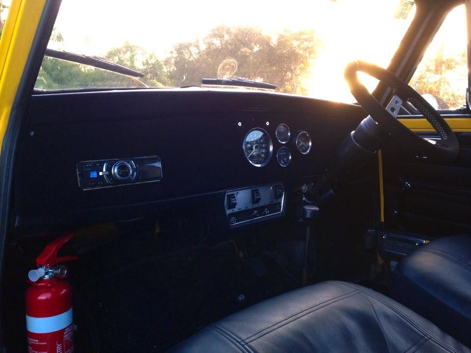
It's been a little while since I've posted or checked u on this forum thanks to uni and work. I've been busy in my rare free time working on a new dash for my clubman, some may have seen these photos before, please forgive me.
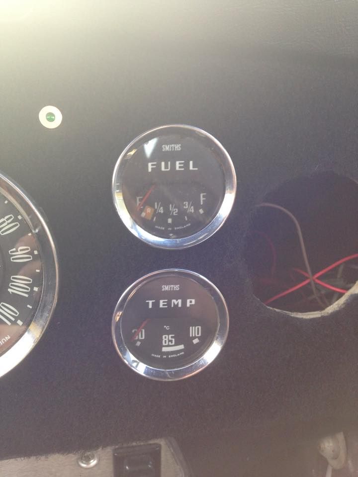
Now it's all made up and looking pretty I need to wire all my guages up. the speedo I've got no worries with and everything there works fine. I'm having trouble wiring the fuel and temp guages however. These are genuine smiths gauges I bought off ebay for a good price. I know the wiring is all there in both of them as in my fiddling around i've got the needle to bounce from side to side with 12V added.
I've not been able to get either of them to work once I've wired them up and am not sure how that even is supposed to be done. I know I've got the right sensor wires as I looked at the wiring diagram and the curcuit board from the original 2 pod cluster.
I suspect that there is a spade for 12v, sensor wire from the sender and a ground. however, I'm not sure if this is the case as that doesn't seem to be prevailing. I also tried wiring in the voltage regulator from the original cluster but that hasen't helped either.
Who can tell me which spade terminals do what? Sorry about the pictures and I cannot find a wiring diagram of a guage of this era online

Image
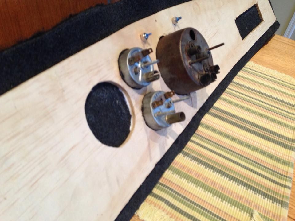
there are 2 spade connctors that are conjoined and one that stands alone on both guages

Image

Image

_________________
-----Better is the enemy of good-----
-1976 Yellow Devil Leyland Clubman-
-1970 Morris Mini Van - Work in progress-


Top
 Profile  
 
PostPosted: Mon Dec 22, 2014 12:49 pm 
Offline
High heel ninja
User avatar

Joined: Sat Apr 10, 2004 6:36 pm
Posts: 4979
Location: Radelaide, South Australia
You need a voltage stabiliser, these gauges run on 10 volts.

Doogie

_________________
I won Hay once, here's the pic to prove it..
Image

Hay, it's not about the car, it's not about the venue, it's about the people that come here. Peter Dwyer, Mayor of Hay NSW.


Top
 Profile  
 
PostPosted: Mon Dec 22, 2014 12:58 pm 
Offline
998cc
998cc
User avatar

Joined: Sat Dec 03, 2005 2:23 pm
Posts: 955
Location: Canberra, ACT
The "sensor" wires will act as the ground and the variable resistance they give is what changes the reading on the meters.

The other connectors will be for power to complete the circuit. The dual connectors will be so you can jump this power between gauges without having to run long feeds for every gauge.

Usually the gauge body will act as a ground for instrument lights - but if using on a wooden dash will have to add an earth wire to somewhere (eg the parcel shelf). I usually run this from the mounting screws.
Hopefully the power to the bulb is self evident.

The gauges may have to run via a voltage stabiliser for accuracy .. but others may be able to clarify / explain that. < Doogie already jumped in...>


Top
 Profile  
 
PostPosted: Mon Dec 22, 2014 3:47 pm 
Offline
848cc
848cc
User avatar

Joined: Thu Apr 03, 2014 10:28 am
Posts: 232
Location: Canberra
Thanks guys for your help so far. Now that I am using the voltage regulator, I'm not getting a resultant 10V. I'm still getting out from the regulator exactly what I am putting in (12.35V). I've tried all the terminals but no luck. should i be using a different type of regulator?

_________________
-----Better is the enemy of good-----
-1976 Yellow Devil Leyland Clubman-
-1970 Morris Mini Van - Work in progress-


Top
 Profile  
 
PostPosted: Mon Dec 22, 2014 3:56 pm 
Offline
998cc
998cc
User avatar

Joined: Wed Oct 23, 2013 10:53 am
Posts: 552
Location: Wollongong NSW
jpodge wrote:
Thanks guys for your help so far. Now that I am using the voltage regulator, I'm not getting a resultant 10V. I'm still getting out from the regulator exactly what I am putting in (12.35V). I've tried all the terminals but no luck. should i be using a different type of regulator?


What type of regulator/stabiliser are you using? 12v is definitely too much, should be a steady 10v for the gauges.

Does it have an 'I' and/or a 'B' labelled on the regulator? You plug your battery 12v into the B terminal and your gauges into the 'I' 10v terminal

_________________
I wish I had some sort of witty quote in my signature


Top
 Profile  
 
PostPosted: Mon Dec 22, 2014 4:16 pm 
Offline
848cc
848cc
User avatar

Joined: Thu Apr 03, 2014 10:28 am
Posts: 232
Location: Canberra
I'm using the regulator from my 2 pod cluster which is a 76 year model. I have wired the regulator so I've got the battery going into the B terminal and the guages are coming of the I terminal. I still am getting 12.35V from the I terminal. I assume thats the issue then?

If i did use 12V on the gauge, shouldn't that mean the guage shoots to the high end of the sectrum? It does move when I apply 12V to it, but only about a milimeter

_________________
-----Better is the enemy of good-----
-1976 Yellow Devil Leyland Clubman-
-1970 Morris Mini Van - Work in progress-


Top
 Profile  
 
PostPosted: Mon Dec 22, 2014 4:29 pm 
Offline
998cc
998cc
User avatar

Joined: Wed Oct 23, 2013 10:53 am
Posts: 552
Location: Wollongong NSW
jpodge wrote:
I know the wiring is all there in both of them as in my fiddling around i've got the needle to bounce from side to side with 12V added.


jpodge wrote:
I'm using the regulator from my 2 pod cluster which is a 76 year model. I have wired the regulator so I've got the battery going into the B terminal and the guages are coming of the I terminal. I still am getting 12.35V from the I terminal. I assume thats the issue then?

If i did use 12V on the gauge, shouldn't that mean the guage shoots to the high end of the sectrum? It does move when I apply 12V to it, but only about a milimeter


So in your original post, you said that you got the needle to bounce? Is that with just straight 12v into the gauge? I assume it went high when the 12v was fed to your gauge? does it only moves a mm when it's running through the reg?

To me (and please anyone correct me if I'm wrong) but it sounds like either an incompatible or faulty voltage reg.

You can buy replacement ones from a member on ausmini made for the smiths gauges. send the user 'Wombat' a PM asking about the stabilisers for the smiths gauges. They're like $20 and they give a steady 10v to your gauges


EDIT::: also, is everything grounded/earthed when testing through the regulator?

_________________
I wish I had some sort of witty quote in my signature


Top
 Profile  
 
PostPosted: Mon Dec 22, 2014 4:40 pm 
Offline
848cc
848cc
User avatar

Joined: Thu Apr 03, 2014 10:28 am
Posts: 232
Location: Canberra
jprior2912 wrote:
jpodge wrote:
I know the wiring is all there in both of them as in my fiddling around i've got the needle to bounce from side to side with 12V added.


jpodge wrote:
I'm using the regulator from my 2 pod cluster which is a 76 year model. I have wired the regulator so I've got the battery going into the B terminal and the guages are coming of the I terminal. I still am getting 12.35V from the I terminal. I assume thats the issue then?

If i did use 12V on the gauge, shouldn't that mean the guage shoots to the high end of the sectrum? It does move when I apply 12V to it, but only about a milimeter


So in your original post, you said that you got the needle to bounce? Is that with just straight 12v into the gauge? I assume it went high when the 12v was fed to your gauge? does it only moves a mm when it's running through the reg?

To me (and please anyone correct me if I'm wrong) but it sounds like either an incompatible or faulty voltage reg.

You can buy replacement ones from a member on ausmini made for the smiths gauges. send the user 'Wombat' a PM asking about the stabilisers for the smiths gauges. They're like $20 and they give a steady 10v to your gauges


EDIT::: also, is everything grounded/earthed when testing through the regulator?


Yes I have had the needle bounce to the top on the temp gauge when i had it wred incorectly. the fuel gauge only moves about a mm when i add 12V. Im confident now that its just the voltage is incorrect and my stabiliser is faulty.

_________________
-----Better is the enemy of good-----
-1976 Yellow Devil Leyland Clubman-
-1970 Morris Mini Van - Work in progress-


Top
 Profile  
 
PostPosted: Mon Dec 22, 2014 6:11 pm 
Offline
848cc
848cc
User avatar

Joined: Sun Dec 19, 2004 7:42 pm
Posts: 178
Location: Melbourne
Neither of these gauges work with a regulator. They work on 12 volts. B for battery T for transmitter.
They both require a sender 83-3 ohms. Not 250-19 used on the post 1964 bimetal gauges.
You can have the clubman fuel sender rewound to suit. The temp senders for these gauges are no longer made. NOS senders are expensive as a consequence.
All others posts are incorrect I'm afraid. :D

_________________
1960 Morris Mini Minor


Top
 Profile  
 
PostPosted: Mon Dec 22, 2014 6:14 pm 
Offline
848cc
848cc
User avatar

Joined: Sun Dec 19, 2004 7:42 pm
Posts: 178
Location: Melbourne
Calibration of the gauges should also be checked. It is very easy to move the two nuts on the back which changes the span and points radically.

_________________
1960 Morris Mini Minor


Top
 Profile  
 
PostPosted: Mon Dec 22, 2014 6:23 pm 
Offline
1360cc
1360cc
User avatar

Joined: Sun Apr 11, 2004 11:32 am
Posts: 12390
Location: Sthrn HiLoLands, NSW, Australia
minijcar wrote:
Calibration of the gauges should also be checked. It is very easy to move the two nuts on the back which changes the span and points radically.


Whew! I've died and gone to Instrument Maker heaven :lol: 8)

_________________
"Show me the Mini!"


Top
 Profile  
 
PostPosted: Mon Dec 22, 2014 6:28 pm 
Offline
848cc
848cc
User avatar

Joined: Sun Dec 19, 2004 7:42 pm
Posts: 178
Location: Melbourne
There are only a few of us left. :)

_________________
1960 Morris Mini Minor


Top
 Profile  
 
PostPosted: Mon Dec 22, 2014 9:33 pm 
Offline
1360cc
1360cc
User avatar

Joined: Sun Apr 11, 2004 11:32 am
Posts: 12390
Location: Sthrn HiLoLands, NSW, Australia
They did Instrument Trades in Melbourne? Was it part of Uni Entrance exams? :lol: :arrow:

_________________
"Show me the Mini!"


Top
 Profile  
 
PostPosted: Tue Dec 23, 2014 12:21 pm 
Offline
848cc
848cc
User avatar

Joined: Thu Apr 03, 2014 10:28 am
Posts: 232
Location: Canberra
Another quick question. I also have a smiths tacho. Will that require 10V or 12V?

_________________
-----Better is the enemy of good-----
-1976 Yellow Devil Leyland Clubman-
-1970 Morris Mini Van - Work in progress-


Top
 Profile  
 
PostPosted: Tue Dec 23, 2014 1:26 pm 
Offline
998cc
998cc
User avatar

Joined: Wed Oct 23, 2013 10:53 am
Posts: 552
Location: Wollongong NSW
minijcar wrote:
Neither of these gauges work with a regulator. They work on 12 volts. B for battery T for transmitter.
They both require a sender 83-3 ohms. Not 250-19 used on the post 1964 bimetal gauges.
You can have the clubman fuel sender rewound to suit. The temp senders for these gauges are no longer made. NOS senders are expensive as a consequence.
All others posts are incorrect I'm afraid. :D


Bugger, sorry for the bum steer jpodge!

_________________
I wish I had some sort of witty quote in my signature


Top
 Profile  
 
Display posts from previous:  Sort by  
Post new topic Reply to topic  [ 17 posts ]  Go to page 1, 2  Next

All times are UTC + 10 hours


Who is online

Users browsing this forum: s-c1293 and 79 guests


You cannot post new topics in this forum
You cannot reply to topics in this forum
You cannot edit your posts in this forum
You cannot delete your posts in this forum
You cannot post attachments in this forum

Jump to:  

© 2016 Ausmini. All garage work involves equal measures of enthusiasm, ingenuity and a fair degree of irresponsibility.