Chapter 2 “Hang on lads I’ve got a great idea” Part 1!
Just to clarify all the design work was done on CAD, using CATIA.
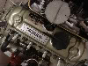
I have been looking for original drawings/CAD for the head for a long time; those that have the data are unwilling to share (Which seems a bit dog in a manger to me but there we go!). So, I had to go to plan B which was to 3D scan a head. Luckily for me we have a scanner at work so scanning the head was a “learning exercise” for me!
Attachment:
Original Head.jpg
Attachment:
Scan Data 1.JPG
Attachment:
Scan Data 2.JPG
This was used to extract the “primary datums” for the design. These are the parts that will be common with the original 5 port. Head stud, rocker pillar studs, & push rod holes, mating faces and bore centres. As well as the architecture of the rocker area.
Attachment:
Datums 1.JPG
Next, I modelled combustion chamber, exhaust port and an initial inlet port. It’s worth noting here that the inlet port position is driven by the head stud on the No4 cylinder… The Arden actually has different ports for 1,2, &, 3 cylinders to 4, however I wanted a common port shape for all 4 cylinders as this would help to make the engine tuning etc. easier. The exhaust is, at this stage, a copy of the No1 cylinder port as I needed a “Peg in the ground” to work around before I looked in to down drafting (Or is that up drafting as it’s the exhaust?). An initial spark plug hole was modelled. It should be noted that there was no chance of using a standard plug, so I modelled around a 10 mm 1-inch thread length plug. Valve guide and spring seat positions were also added. Finally, I put an inlet manifold mounting face in. This is the same as the Arden face (so I could use Arden gaskets!) Rotational orientation of these would be tuned throughout the design process. I wanted them as vertical as possible so the bolt pattern would have a good spread to support the heavy manifold. The result you see is the compromise driven my other factors such as the injectors and spark plugs.
Attachment:
Chamber Ports and Plug.JPG
Attachment:
Including Inlet Face.JPG
Attachment:
Cutter Top.JPG
Attachment:
Taking Shape.JPG
As you can see very quickly things are taking shape, so the next stage is to start “blocking” things up. I used a material minimum thickness of 6 mm, so everything developed so far was thickened to this to start building a solid model.
What followed was a lot of iteration, very hard to show with images. I need to maintain a minimum wall thickness of 6 mm, while also maintaining a reasonable water jacket.
The injector position had to be developed. Old school thinking on the injectors it that they should point at the back of the valve, more modern thinking drives the injectors back up the inlet track, as modern injectors atomise the fuel better. As the injectors are in the head, I tried to get them as close to pointing at the valve as possible. This area of the head was the biggest challenge; getting the port, inlet flange, spark plug and injector boss to all fit around the rocker cover and head studs. So, there are of course compromises. Injector position is good, but not perfect, it is also leant over my 5 degrees which makes for more complicated machining on the injector rail. The spark plug is a very snug fit and the inlet flange bolts are rotated more than I would like.
Attachment:
Port.jpg
Exhaust port design was also studied, I have no images of this, but it soon became apparent (as I suspected) that up-drafting the ports was not really a viable option. Due to the push rods & rockers and rocker cover I would only be able to get about 3-5 degrees. And even that would compromise the water jacket. Making a unique rock cover (like the Pinion head) would help but that was beyond my design remit. Therefor I decided to keep a “carry-over” design. I would be able to use an off the shelf 8 port exhaust manifold, not a bad idea when you think how much else I needed to design and engineer!
Attachment:
Pinion.gif
At the front of the head I wanted to copy the 5 port head and run the water jacket under the plugs to aid coolant flow. To do this drove the head a long way forward as the plugs are at a much shallower angle to get under the inlet ports. You can see the “chin” on the front of the casting. This also allowed me to get water to all 8 of the front water jacket holes in the top of the block. I did not want to block any of these off or be forced to machine channels into the face of the head, as seen in some 7 port designs.
Similarly, the Oil gallery follows a similar route to the 1275 casting, but with one more drilling due to the reduced length of the head (No thermostat housing)
Couple of points about the model developed at this time: I did develop a high-level concept of the tooling design, but the model has no draft angles and many overhangs. The reason for this will become apparent later. I am also modelling a finished machined head. There is about 3-4 months covered in this chapter, and many many many hours of CAD.