CHAPTER 14 - More Body Work
Hi All,
I guess its time for an update again. I have been spending huge amounts of time getting the bodywork finished so it can be sent off to the spray painters to have the top coat done. This is the last major thing that has to be done. There is an enormous amount of minor things still to be done though!!
Last chapter I made some in-roads into doing some body mods to individualise the car, and this chapter is no different. Some of them are from necessity, to house some of the equipment forced upon me from the Starlet conversion, while some I have chosen to do just to make the car stand out.
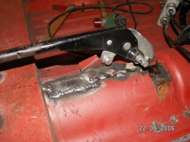
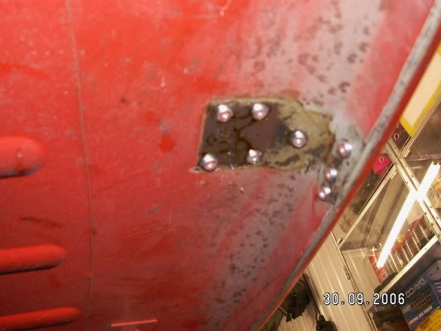
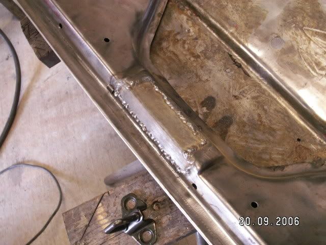
While I was working on the tunnel (last chapter we filled the hole in the floor where the rod change went), I decided to mount the Starlet gearshift mechanism. To do this I put the seat into the shell, and measured up exactly where the shifter would go. Using a very exact science of closing my eyes and letting my hand fall to exactly where I believed the shifter should be, and it was right on top of the brake lever. Yes, that far back. So the first thing to do was relocate the hand brake further to the rear by by about 100mm. This is where it ended up. The small plate in front was the result of a skin tear, so I plated it just to make sure.
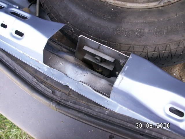
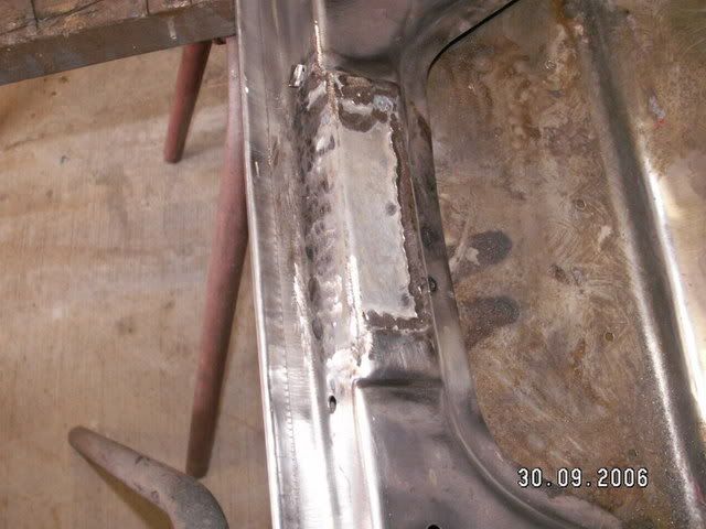
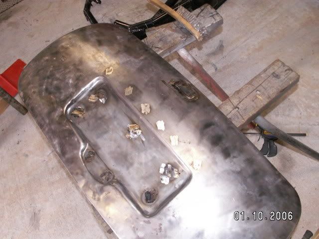
Now, to mount the gearshift mechanism. From most of the spots people have mounted theirs, it looks to me that it is way too far forward (just my opinion, bearing in mind I am vertically challenged!), most likely because people dont want to move the handbrake lever (also my opinion!). To start, I cut out the 'crowns' out of the rear two mount holes, that is the raised platforms that contain the captive nuts that the plastic cradle bolts to. With the crowns cut out, I welded them straight onto the floor crossmember in the spot I had previosuly marked. To mount the front two bolt holes, I cut the whole strip out of the front, with mounting holes attached, bent the ends down, and then welded them onto the transmission tunnel. This is how it turrned out.
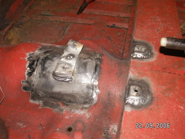
As you can see from the pic, the profile is nice and low, so carpet has a better chance of sitting over it and not looking like Quasimodo's back!
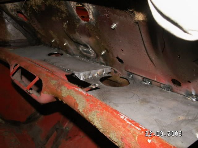
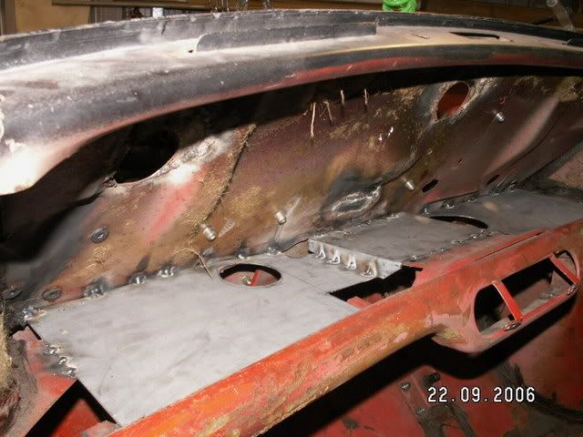
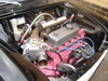
Next up came the dash, or rather, what was under the dash. Because there was so much equipment to be stored behind the dash (ECU's, boost controllers etc), I decided to cut out the spider brace underneath, and plate it with 1.2mm sheet, to make a sort of shelf. The shelf is made in two parts, with one part spanning the entire wdth of the dash, and the second part reinforcing where the heater controls were. The underside will be sprayed with a bit of sound deadening to stop the drumminess. This is the end result:
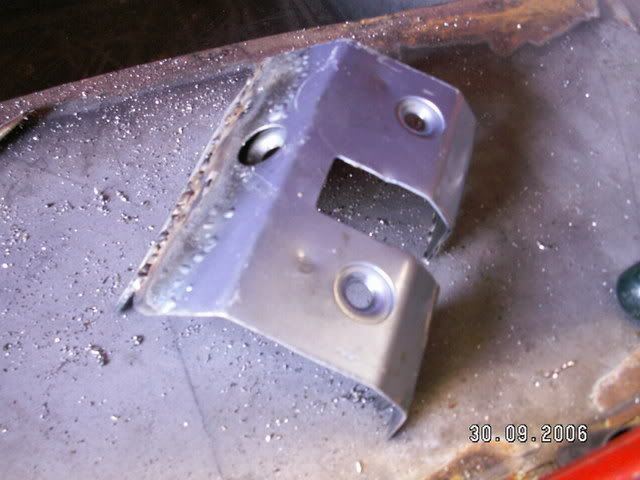
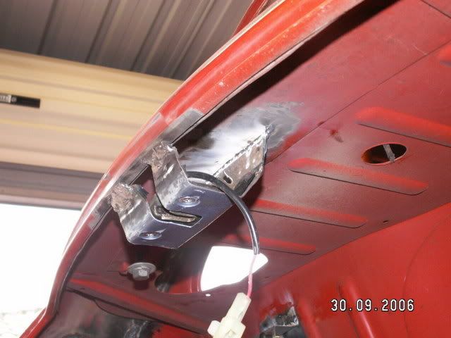
Now it was time to attack the panels proper - the external stuff. I decided that for the boot, I wanted a flush finish. No badges, no handle, nothing protruding except the number plate light. So, I decided to use the electric internal hatch release off the AWD Civic (Project Number II) and graft that onto the Mini. Firstly, was the removal of the latch on the inside, upper lip of the boot. I removed this using a spot weld remover (If you havent got one, get one - great tool!) This is where it had been originally located:
And this is what was removed. See how the spot weld removing tool just cuts around the spot weld to one layer deep. The latch almost fell off at the end. Then just grind off the spot weld 'dimples'.

The Mini latch will now be replaced with the Civic latch. Firstly we cut out the section out of the Civic where the latch had been located with the air hacksaw. This is where the tongue in the hatch comes to mate up with the latch.
And this is the part that was cut out.
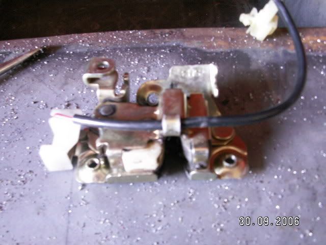
Because we wanted this.....its an electric and cable release for the Civic hatch. Now we will have a fully functioning remote release for the Mini boot.
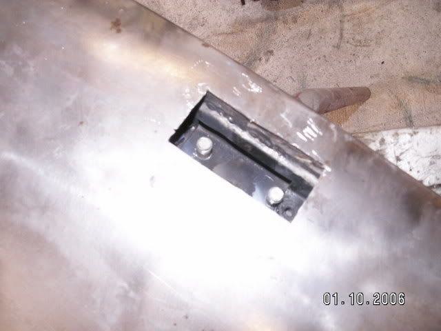
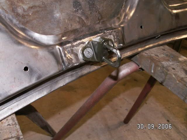
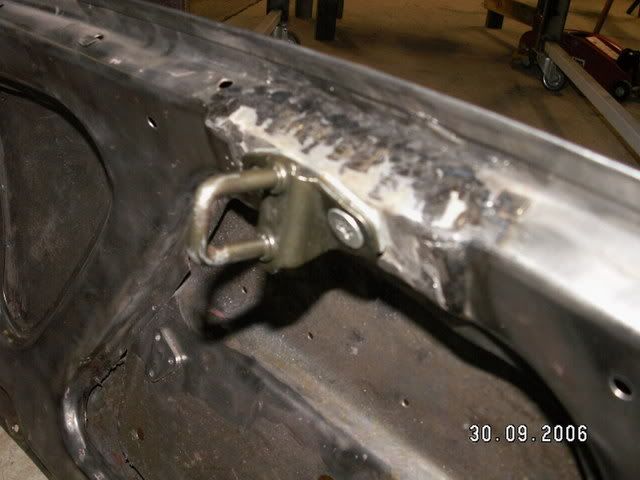
And this is the part welded into place, with the electric strike mounted.
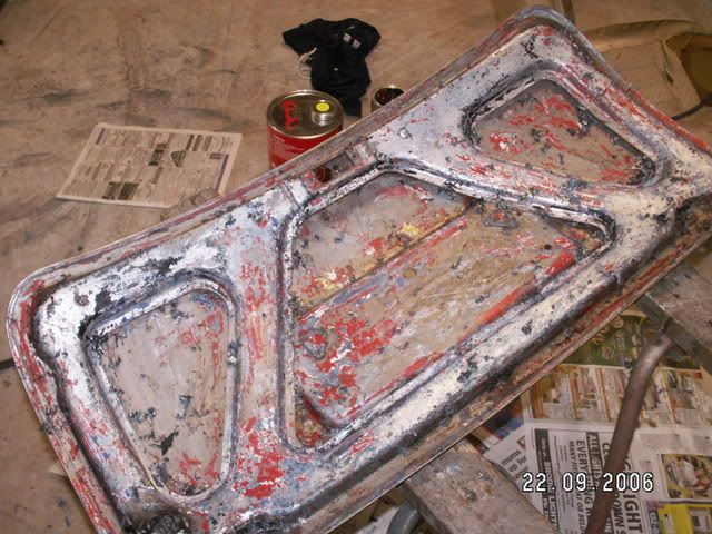
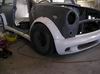
Next up came the task of mounting the tongue onto the Mini boot lid. Before I did any welding etc, I decided to fully strip the Mini boot back to bare metal. This would have to be done regardless, as with a full colour change its the best way. Anyway, it had need of some TLC in the panel beating department as well. What I couldnt get over, was how many layers of paint were on this thing - I counted four, and that was just the topcoats....
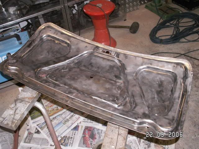
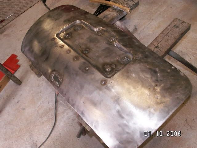
This was the end result after a couple of hours with the stripper and wire wheel. On the left you can see the tab welded into place for the gas strut. This will mean that when the boot is remotely released, it will open under its own steam (slowly and precisely), pushed by the strut. The strut will also act as the opening limiter. The gas trut came from a Toyota Camry bonnet.
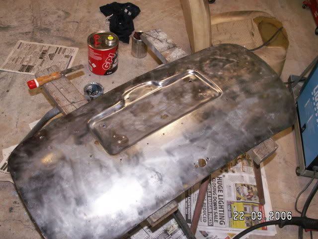
With the boot fully strpped back to bare metal, it was time to plate over where the MIni handle had been, and also the Mini internal latch mechanism. Using 1.2mm plate, simply cut to size, and weld in. You can see the Civic tongue lying next to the boot lid in this picture.
And then grind off flush with the disc sander.....
Next came the task of filling in where the handle protrudes through the boot lid skin, and all those other nastly little holes where they mount the badges etc. The holes where the handle protrudes through, was just cutout to a square shape, to make it nice and easy to weld in the new patch.
And then all the other little holes filled in as well as the plate for the sqaure cutout.
Then of course, we just grind off the welds flush with the skin using the flapper disc...
The last job of the day was mounting the tongue. It had to be positioned exactly, so it would enter the latch without binding and catch the striker just right. A couple of trial fits and the location was marked. I drilled and tapped (hence why we use 1.2mm plate) the boot lid to mount the tongue, using the factory screws.
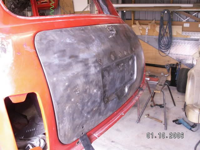
And this is the end result, a flush bootlid with remote release either by key fob or internal lever release next to the drivers seat. Now all I need to do to finish it is some filling and sanding.


