Ausmini
It is currently Tue Jul 22, 2025 7:54 am

All times are UTC + 10 hours


Post new topic Reply to topic  [ 8 posts ] 
Author Message
 Post subject: Alternator wiring...
PostPosted: Sat May 30, 2009 2:22 pm 
Offline
998cc
998cc
User avatar

Joined: Sat Dec 03, 2005 2:23 pm
Posts: 955
Location: Canberra, ACT
Image

Getting clubman ready for Hay and the alternator is playing up ...
so have a new 70 amp version (eg 90's mini) for another project thought I 'd put that in....

but of course now confused on wiring....

Ok I have 3 wires :
Brown/Yellow charge indicator.
Green (small lucar connector)
Heavy Brown wire

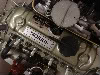
On the alternator - pic above...
Heavy wire to B+ (held on by 10mm nut)
But others ?
W terminal has a screw on cover.
I've attached the Green to the lucar termial ajoing the B+

The brown/yellow to the the other small lucar up the top (the 3 connectors are all connected)

There is electronic control gizmo that has a yellow wire going to it (inside the casing) (as shown in diagram)
Would this be the regulator ? - and does it need to be powered (I found this with the Charade alternator in the race car)

Currently Alt light constantly on and voltmeter on dash steady at 12v. (this was same symptoms with other alternator)
If I put a voltmeter to the B+ out put seeing erratic 12v <-> 2v reading but nothing above. (volts from battery ?)

Photo might help...

Image

Anyway I'm now late for another engagement ... be tomorrow before I check back on comments..
Hopefully as I'm in a rush have missed something silly....


Top
 Profile  
 
 Post subject:
PostPosted: Sat May 30, 2009 3:23 pm 
Offline
SooperDooperMiniCooper ExpertEngineering
User avatar

Joined: Fri Apr 29, 2005 9:46 am
Posts: 18887
Location: Under the bonnet son!
Your heavy brown wire is the output charge from the alternator, easy enough.
The W terminal is for tachometer ripple feed when they are fitted in modern cars. You won't need this one.

I believe you will find that the indicator warning lamp (brown/yellow) will go to the D+ terminal. You need to find out what the green is actually connected to. The green (unless somebody has fiddled with your wiring ) is for your temp sender. The terminal it's occupying might be the switched terminal from the igniton switch.

_________________
SooperDooperMiniCooperExpertEngineering

All garage work involves equal measures of enthusiasm, ingenuity and a fair degree of irresponsibility.


Last edited by Mick on Sat May 30, 2009 11:20 pm, edited 1 time in total.

Top
 Profile  
 
 Post subject:
PostPosted: Sat May 30, 2009 8:37 pm 
Offline
the King of Bling
User avatar

Joined: Thu Jun 03, 2004 11:11 pm
Posts: 19858
Location: Baulkham Hills
yep I'v been studing a few wire diagrams of late and no Green wire goes to the alternator only Browns and or with a colour trace.

_________________
Stop Licking the Dog...I Don't Care Who Started It


Top
 Profile  
 
 Post subject:
PostPosted: Sat May 30, 2009 8:59 pm 
Offline
religious status
religious status
User avatar

Joined: Fri Mar 19, 2004 6:19 pm
Posts: 39755
Location: near Baulkham Hills, NSW
Early cars with the old Lucas 15AC alternator and separate regulator had a brown/green wire from it to the field terminal on the alternator.
All later alternators including yours have an internal regulator instead.
Only wires connected are the thick brown ones (usually 2) to the 12V+ output, and the brown/yellow indicator light wire.

Bosch alternators (ex Falcon, etc) when put in Minis have an additional 12V feed from the switched fuse. Yours may need this one too, I'm not up on Rover alternators.

_________________
DrMini- 1970 wasaMatic 1360, Mk1S crank, 86.6HP (ATW) =~125 @ crank, 45 Dellorto (38 chokes), RE282 sprint cam, 1.5 rockers, 11.0:1 C/R. :mrgreen:


Top
 Profile  
 
 Post subject: Green Wire
PostPosted: Sun May 31, 2009 6:36 am 
Offline
1275cc
1275cc

Joined: Thu Dec 09, 2004 6:57 am
Posts: 3022
Location: JIMBOOMBA QLD.
From Memory that spade connection next to the B+ terminal bolt on these Alternators is another B+ which is used for a Noise Suppressor. That Greenn wire should not be there. The Green wire might be a wire that comes from the Fuse Box for either the reverse light switch feed ot the Windcsreen washer pump in that vicinity. Disconnect it and see if it has power to it when the ignition is turned on. I sell these alternators and they should only need a heavy cable carrying the B+ to the battery and a warning light wire. For the B+ you have a choice of using the 2 large spades or the terminal post marked B+ and the smaller spade near the two large ones is the warning light terminal. Always check that you have a good and heavy enough lead to carry the Current that the Alternator is capable of pushing out running to the battery. For this Alternator I would use 2 X 6 mm wires . Or the original Brown charge wire plus another 6 mm wire. You need cables that can carry 70 Amps with ease. Make sure you have a good B+ connection to the battery source.

_________________
DID I MENTION THAT I AM THE BEST SUPPLIER FOR MINI ELECTRICAL PARTS AND REPAIRS?
"Let us remove your "SHORTS"


Top
 Profile  
 
 Post subject:
PostPosted: Sun May 31, 2009 8:53 pm 
Offline
998cc
998cc
User avatar

Joined: Sat Dec 03, 2005 2:23 pm
Posts: 955
Location: Canberra, ACT
Thanks for all that - makes sense.

(What I hadn't said before was the other alternator was Mitsubishi (brand) - so may have required the green feed in a similar way as the Charade alternator. Will remove to avoid the Lucas smoke escaping and add extra from the output).)

As both alternators are having same problems looks like fault may lie elsewhere - probably an earth :( .... though getting power through from battery for starting and running .. ???

Didn't get a chance to look at today......


Top
 Profile  
 
 Post subject:
PostPosted: Mon Jun 01, 2009 6:47 pm 
Offline
998cc
998cc
User avatar

Joined: Sat Dec 03, 2005 2:23 pm
Posts: 955
Location: Canberra, ACT
Yep that was it ..... bad connections... :)

Removed a cleaned up wires at the solenoid... and added extra 6mm feed ...(and removed the green wire).
Fire up and still have warning light, 12 volts...
run up to about 3,000 - light still brightly on -
gun it and around 4,000 voltmeter goes to 14v and light out - stays that way back at idle after that.

Went for a drive round the block..... and 15 km later :? and just shy of Uriarra Crossing - remember still had the boot open !! :shock: :oops:
( thankfully everything still there - and Canberra traffic back in town just ignored it ! :roll: ) .
Quick run up Fairlight Rd and - yep - handbrake works.....
(but work boots aren't best for any finesse or is that just lack of practice :P )
- and head back home again.
Not a waiver or voltage drop on the entire trip...
(weird the word f l i c k e r seems to be censored)

Switch off and restart - and same symptoms .... so will work my way through the other connections and clean them up.


Top
 Profile  
 
 Post subject:
PostPosted: Mon Jun 01, 2009 8:19 pm 
Offline
998cc
998cc
User avatar

Joined: Tue Sep 14, 2004 7:06 pm
Posts: 869
Location: Cobram, VIC
If you have to rev the guts out of your car for the red light (charge light) to go out it sounds like your battery sense wire needs looking at. Generally when wiring up an alternator you have three wires not including tacho. Battery which is usually 6mm or thicker, red light (charge), and battery sense. The alternator will charge without the battery sense wire, however, this wire is important as it tells the regulator when to cut back on voltage.
I had an RACV call last month where the customer had fitted a new alternator to a Hiace van, forgetting to connect battery sense. This resulted in the battery boiling and charging to 17 volts, killing all globes in the dash, headlights, tail lights and the GPS plugged in to the cigarette lighter socket.
When I fitted a falcon alternator to Lynda's first Mini I used the RE60 regulator as it displays the wiring pins needed.

Also... try a heavier wattage globe in your instrument cluster. I know it sounds Irish saying it now after all I have just written but I just thought about it now. This will cause the exciter diodes to excite earlier, therefore taking out the red light circuit. The red light needs 12 volts both sides of the globe in order to allow it to go out.

Hope this helps you.
Regards,
Damo

_________________
Image

1978 Leyland Mini 998LS All Original *Sally*
2002 Mini Cooper *Coopa*


Top
 Profile  
 
Display posts from previous:  Sort by  
Post new topic Reply to topic  [ 8 posts ] 

All times are UTC + 10 hours


Who is online

Users browsing this forum: Barkfast and 77 guests


You cannot post new topics in this forum
You cannot reply to topics in this forum
You cannot edit your posts in this forum
You cannot delete your posts in this forum
You cannot post attachments in this forum

Jump to:  

© 2016 Ausmini. All garage work involves equal measures of enthusiasm, ingenuity and a fair degree of irresponsibility.