miniature wrote:
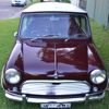
I have a '71 Mini K, which at some point in its life, had a metro A+ 998 transplanted. During my restoration of the car, I decided to get a wiring loom from Minispares that was meant for a MK1 Cooper with alternator (part 5L672).
I haven't compared wire for wire, but in theory, the loom you bought should work (there are some differences, read on), however, what I have noticed is that the UK looms seem to use a smaller gauge wire than the Ozzies did. There is a company here in Oz - Vintage Wiring Harness - who can supply an 'as original' loom but they only supply to order, which can be good, because if you want some modifications (eg LH drive), they can do it when they make it.
http://www.vinwire.com.au/miniature wrote:
I don't think that any of the existing diagrams in the Haynes manual seem to match up with this loom after examining them.
The diagram for the MKI Cooper S / Deluxe 850 should be the same.
miniature wrote:
First, I figured out that this loom is probably designed for an older Mini with the old-style starter solenoid that is separate from the starter. Since I have an A+ engine, I have the later style solenoid integrated with the starter. Is there any way I can use this ignition wiring with my A+ starter solenoid? Would anyone happen to know what modifications I would need to make if they are needed? On the set of wires going to the starter solenoid, I have the following:
1. A brown wire with a small female spade connector
2. Two brown wires merged into a big female spade connector
3. A white with red stripe wire with a small spade connector (I think this is for cranking the starter based on Lucas wire color codes)
The starter solenoid has a big male spade connector and one small male spade connector. Currently I've connected wire #1 to the small spade connector on the solenoid and wire #2 to the big spade connector on the solenoid. I don't think this is right because I can't seem to get power to circuits that should be 'always on' such as the blinkers. I was surmising that it might be because the ignition wiring must be hooked up first for the 'always on' circuits to be live.
All the BROWN wires need to connect to the battery +ve on the Solenoid. They come up from the front vailence and so should reach no problem. The only 'wire' you will have to alter (extend) is the main battery cable itself. The White wire/ Red trace is the 'Start' wire. It engauges the solenoid to operate the starter motor. The should be a seperate stand alone terminal on the solenoid. It goes on to that.
The blinkers are fused and come 'alive' via the ignition switch. They are not alive all the time.
miniature wrote:
The second issue I'm dealing with is the headlight wiring. There are many different headlight-related wires and I need to figure out whether they should be wired to each other or whether they were meant to be used in conjunction with a relay. There are three sets of headlight-related wires on this loom:
At the front grille area:
1. Blue-red bullet connector
Low or Dipped Beam2. Blue-white bullet connector
High or Main Beam3. Red bullet connector
Parking Lightsminiature wrote:
Short set of wires at center binnacle on dash:
1. Blue bullet connector from HEADLIGHT switch
2. blue-red bullet connector to LOW Beams
3. blue-white bullet connector to HIGH Beams
These went to the Head Light Dipper Switch. On the Mini K, this was actually on the steering column as part of the blinker switch, however (and this is one of the differences with the loom) on the MKI Cooper S, it was floor mounted on the centre of the toe board, to be operated by your foot. Shouldn't be a big problem, you may have to unwrap some of the loom tape to pull them back (or they may reach) to the steering column with the blinker switch wires.
miniature wrote:
Another longer set of headlight-related wiring that appear to be for a dash switch:
1. Blue with a spade connector
2. Red with a spade connector
3. Two reds merged into one spade connector
4. Brown-blue with a spade connector
Does the above wiring seem like wiring for a relay? I can't make sense of what should be plugged in where based on what is there...
These go to the Headlight / Parker Switch (it is a single switch with 3 positions). There were no factory fitted relays to this model.
Just some other 'basics' that may help with wire colour coding;-
BROWN alive all the time, NOT fused (ie stright off the battery).
PURPLE alive all the time, but fused. (in this model, it was only the Interior Light and Horn that was connected on this circuit).
WHITE alive via the ignition switch, NOT fused.
GREEN alive via the ignition switch, fused.
BLUE is the Headlight circuit
RED is the Parker / Taillamp / Instrument lamp circuit.
Trust this is of some help.
<EDIT>
I think Convertable Mini beat me to it while I was writing & having breakfast.
Convertible Mini wrote:
PS.
TRY NOT TO LET THE SMOKE OUT OF THE WIRES OTHERWISE NOTHING WILL WORK. LUCAS SMOKE IS VERY EASY TO LET OUT BUT VERY EXPENSIVE TO REPLACE.