Ausmini
It is currently Mon Nov 11, 2024 5:47 am

All times are UTC + 10 hours


Post new topic Reply to topic  [ 105 posts ]  Go to page Previous  1 ... 3, 4, 5, 6, 7  Next
Author Message
PostPosted: Mon Sep 01, 2014 5:10 pm 
Offline
resident alien
resident alien
User avatar

Joined: Fri Dec 31, 2004 1:08 pm
Posts: 3278
Location: Outta this world!
The thread... it just stopped! NOOOOOOOOOO!!!!!!!!


Top
 Profile  
 
PostPosted: Mon Sep 01, 2014 5:41 pm 
Offline
Causing or creating vexation

Joined: Wed Jul 21, 2004 10:32 pm
Posts: 19116
Where the hell have you been?


Top
 Profile  
 
PostPosted: Mon Sep 01, 2014 10:18 pm 
Offline
resident alien
resident alien
User avatar

Joined: Fri Dec 31, 2004 1:08 pm
Posts: 3278
Location: Outta this world!
Lurking :)


Top
 Profile  
 
PostPosted: Wed Sep 03, 2014 3:15 pm 
Offline
848cc
848cc
User avatar

Joined: Mon Mar 04, 2013 9:02 pm
Posts: 154
Location: East Melbourne, Australia
Noooooo!!! Just been glued to my phone for the last half hour reading this post instead of doing my homework!!! And it's all abruptly come to an end on the 8th page!! :'(
Amazing work tricky!!


Top
 Profile  
 
PostPosted: Sat Sep 06, 2014 10:23 pm 
Offline
848cc
848cc

Joined: Thu Apr 26, 2007 8:16 pm
Posts: 85
I've heard it's coming along nicely !


Top
 Profile  
 
PostPosted: Mon Sep 08, 2014 7:45 pm 
Offline
1275cc
1275cc
User avatar

Joined: Fri Jun 17, 2005 10:31 am
Posts: 3183
Location: Burpengary, Queensland - Home of Tricky Performance Engineering
Guys,

Sincere apologies for the lack of updates, its been very hectic of late with lots going on. I think its time though to share some more with you all.

Last time we conversed we had finished the upper rear subframe mounts, and then filled our spare time in with filling in some factory floor holes - time to crack on!!!

I decided to have a bit of a detour from doing the structural stuff on the Mini and do some more 'cosmetic' stuff per se - namely the boot lid. The boot lid would have to be altered to allow for air to pass through it and let all that engine -produced heat escape somewhere - hoepfully vented out the back. Leonidas came with all the hanging panels, and when I got him I really didnt inspect too closely the condition of the panels - I knew that the boot lid had a few bubbles in it.

Upon closer inspection, the boot lid was a bit more rusty than previously thought. Now if we were doing a resto, I would have spent the time and effort saving the lid to make the car original, but with Leonidas - seeing as virtually nothing will be original - its a different story. The boot lid will have most of the support structure cut away, and vents added with some sort of screening to stop hands and other unwanted intruders entering into the engine space - it was just too uneconomical to save.

The bootlid didn't look too bad from the outside:
Image

Getting medievil on its ass:
Image

But upon closer inspection:
Image

Image

Fixing it would have cost more than buying a fibreglass skin from ABS - so instead of mucking around with it, it was binned in favour of a fibreglass unit which would be a few grams lighter.

Moving on - now that we knew where the rear axle centreline was going to go, it was time to cut out the rest of the wheel arches. I had been putting this off until the bodykit arrived and I could test fit the rear flares up to the body to see how they aligned with the wheel opening. They fit wasnt too bad, so it was time to delete the inner guard, and open the space in the 'back' right up.

Not much left now, but this had to go:
Image

And its brother on the other side:
Image

A few minutes later:
Image

Gone!!
Image

Gotta love that openess and spaced that we have created!! With the wheel arches gone, it gave us more room to move around and not bang into anything, so it was time to press on with more structural work. The design of the rear subframe called for it to be solidly mounted in no less than eight (8) seperate spots - after all, we wanted this car to be as rigid as we could psossibly make it, without adding too much weight. Now with the arches gone, the next set of moutning points to be done was the lower rear ones.

These were to be done in a similar vein to the upper rears we did earlier - design, mock-up, cutting, plating and then finishing. First up was some design in CAD - Cardboard Aided Design, which also helped us do the mock-up. The overriding design criteria was that the subframe had to come out from underneath, with the motor/suspension/driveline all still attached, and then the engine/driveline would come out from the top once the subframe was out - this was not easy to design in, as consideration had to be given not only to where the mounts were located, but what shape they were to take.

CAD action:
Image

Image

Cutting out the upper and lower plates from 3mm:
Image

Passenger side welded in:
Image

Making sure to get good penetrations all the way through:
Image

Drivers side:
Image

Once more good weld penetrations:
Image

Then we had to think about fixings and fasteners - once more captive nuts welded to the inside of the vertical faces would act as strong and secure mounting posotions for the subframe. Here are the front plates bent up and ready to be welded into position with the captive nuts already in place:
Image

Welded in place and dressed, passenger side:
Image

Drivers side:
Image

Next comes the finishing of the structural works, and some nifty pipe bending - stay tuned.

Cheers,
Tricky

_________________
"Not Speeding Officer..........Qualifying"


Top
 Profile  
 
PostPosted: Tue Sep 09, 2014 8:20 am 
Offline
848cc
848cc
User avatar

Joined: Thu Sep 12, 2013 3:10 pm
Posts: 358
Location: Bentleigh, VIC
Tricky's back!! :D :D :D

Nice work.

_________________
1998 Rover Mk VII
2001 Honda CBR 929RR (street)
2014 BMW S1000RR (track)
Image


Top
 Profile  
 
PostPosted: Tue Sep 09, 2014 3:28 pm 
Offline
848cc
848cc
User avatar

Joined: Wed Mar 14, 2007 3:50 pm
Posts: 404
Location: MORNINGTON PENINSULA
Nice work brother

Cheers Hallsey


Top
 Profile  
 
PostPosted: Tue Sep 09, 2014 9:45 pm 
Offline
998cc
998cc
User avatar

Joined: Mon Jan 16, 2006 1:15 pm
Posts: 683
Location: Melbourne
Looking good Tricky!


Top
 Profile  
 
PostPosted: Sun Sep 14, 2014 9:44 am 
Offline
1275cc
1275cc
User avatar

Joined: Fri Jun 17, 2005 10:31 am
Posts: 3183
Location: Burpengary, Queensland - Home of Tricky Performance Engineering
Hi Guys, thanks heaps for the kind words and the support for the project, means a lot...

Anyway, I thought I would update this thread again, as the build is actually a fair way ahead of where the thread is, and I need to be a bit more diligent about keeping this updated - sorry Justin!!

And speaking about Justin, can I just say what a top bloke he is - not for paying the invoices on time, but for his unwavering focus for the project. This project is fairly lengthy (well, not if you compare it to The Cat, but that is another story!!) - and a lot of people would have diluted the project down just to reduce the time or save some dollars - not Justin - his steadfast commitment to the original design intent - that of a race-ready/fast road car is worthy of mention. His vision for the car in his minds eye is resolute and unbending - that folks takes cohones. Justin also asks a lot if questions and even challenges me on occasions if he thinks that an area of design is not in the best interests of the project or could be improved - this shows that he wants to be involved, have input and share the outcomes (good or bad!!). For instance, Justin has brokered a deal with Skunk2 in the USA to supply some engine parts for the F20B - he did this on his own volition without any prompting from me as a way to improve the end result. We thank Skunk2 for being a part of Leonidas, and I also personally thank Justin for having the stones to approach Skunk2 in the first place - well done mate!! :wink:

Anyway, enough about Justin and more about me, err, Leonidas..... :roll:

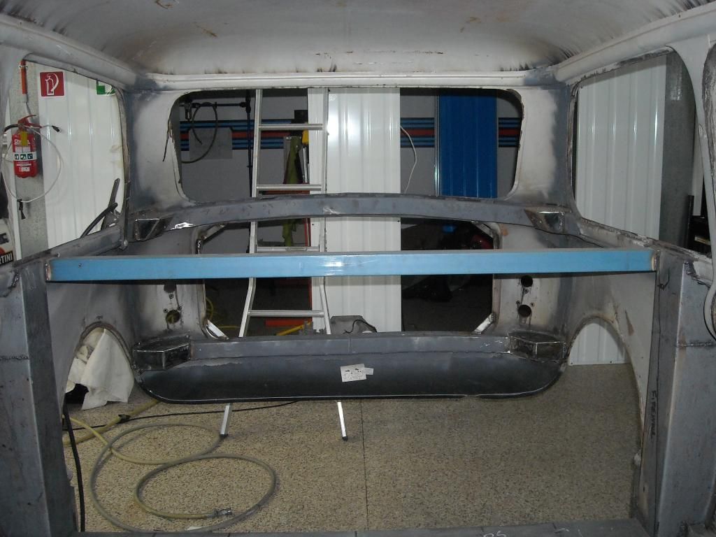
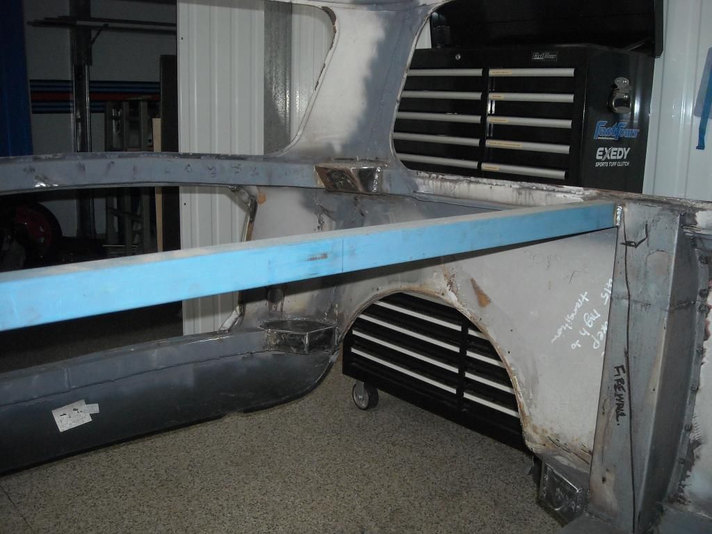
Last time we met we had finished the lower subframe mounting points and binned the original bootlid in favour of a lightweight fibreglass item because it was too uneconomical to repair. Moving on with the structural side of things, the last element of the sutructural support is ready to be done - the front upper mounts. This structure has to do some other tasks as well - it needs to provide mounting points for the subframe as previously said, provide support for the 12mm Lexan window, provide a mounting point for the firewall and provide hardpoints for the racing harness mounts. While this sounds like a lot of multi-tasking, the structure is actually very simple- its basically a transverse piece of RHS welded in place. The location for the bar was also set in place - basically to the rearmost edge of the upright bulkheads. This will allow the firewall to slope backards slightly, and provide some space behind the seats for the rollcage install, mounting the ECU and other bits to the firewall between the seats and also a small bit of storage behind the seats for things like helmet bag and the occasional dead body (wtf I hear you say, you will never get a dead body behind those seats - and you are right, wont fit - delete the part about the dead body damnit :evil: )....

A piece of 40x40x2.5mm RHS was chosen for the task. This will allow a flat surface for the 12mm Lexan to sit on, and also a flat face for the firewall to butt up to. It was cut to size and welded in place:
Image

Image

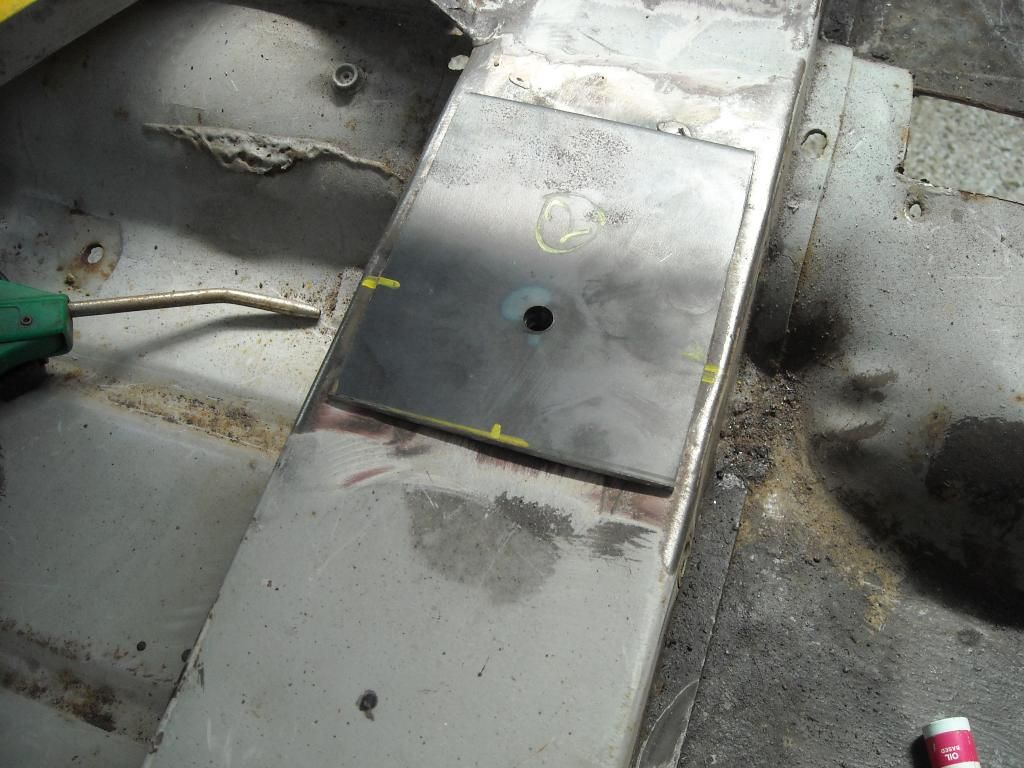
Note: What I havent shown is the mounting points for the subframe - 2mm plate with captive nuts welded onto the bar. My apologies for this as the camera took a dump! :roll: These points will show up in later photos of the subframe itself mounted up....

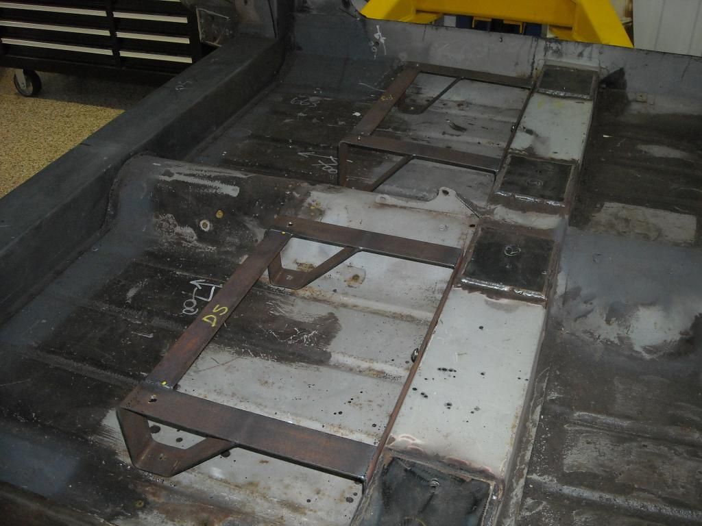
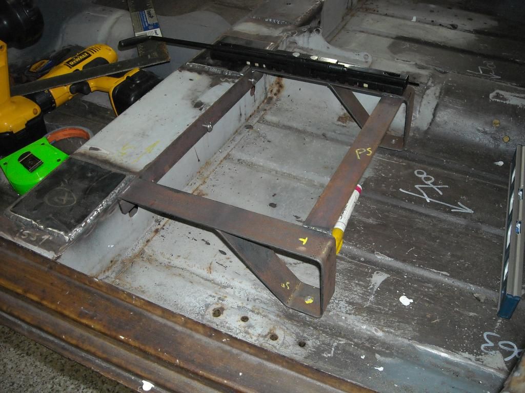
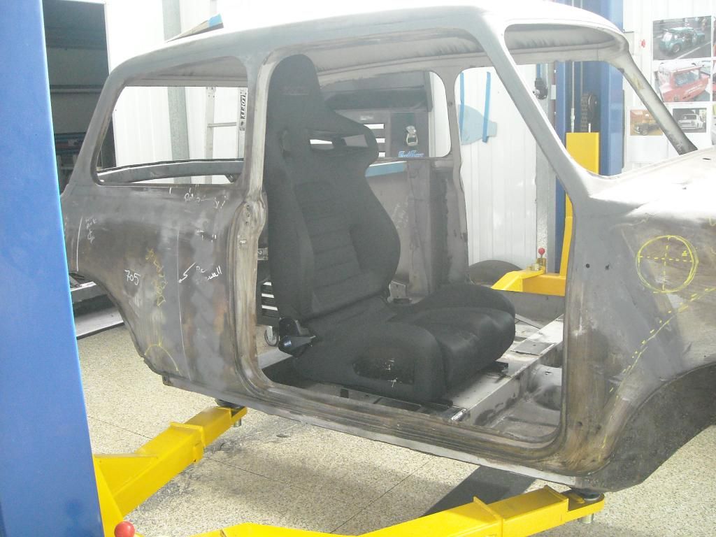
With the bar in place I could check seat fitment. Justin had chosen a nice set of Sparco 333's for Leonidas. They were a really good choice - lightweight, comfortable and very supportive and they also came with the apertures for the harness shoulder straps built-in. I made up some seat bases for the seats from 40x3mm strap - it ididnt need to be anything too heavy, but substantial enough to cater for the loads imposed. The back part was bent into a U-shape, while the front was designed to butt up to the original Mini transverse crossmember as the front support element (as per original Mini). The front of the seat rails is mounted directly on top of the crossmember, so this aread has to be reinforced. I used some 2mm plate, with captive nuts wleded to the underside, and then welded those to the crossmember at the four bolt locations - a bit overkill but there is zero chance of shear now:
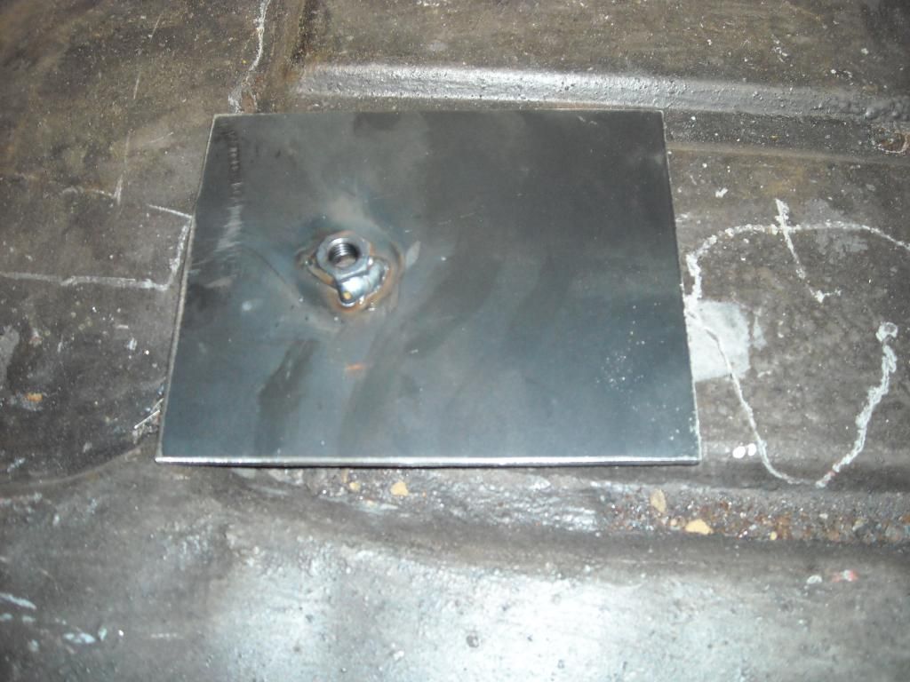
Image

Image

3 x M8 grade 8.8 bolts hold the front part of the seat base to the crossmember using nutserts into the crossmember, while at the part 2xM8's go through the reinforced floor to anchor the rear of the seat base:
Image

Image

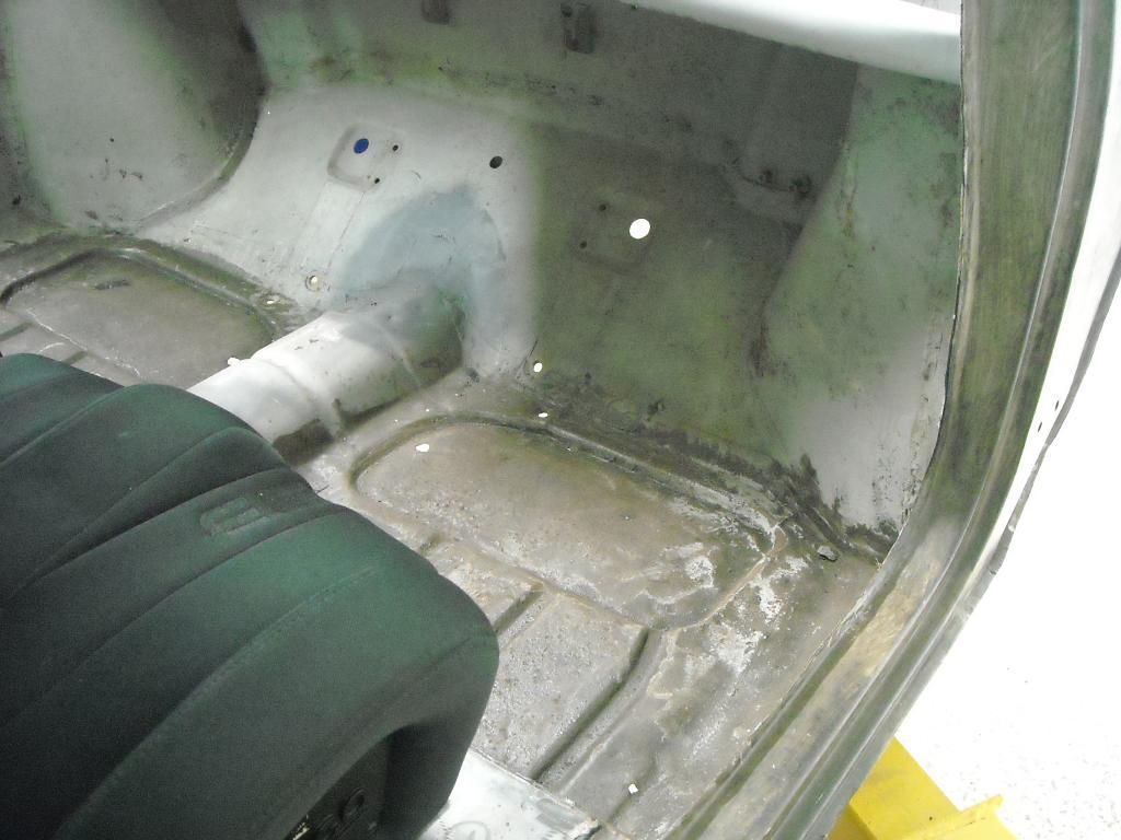
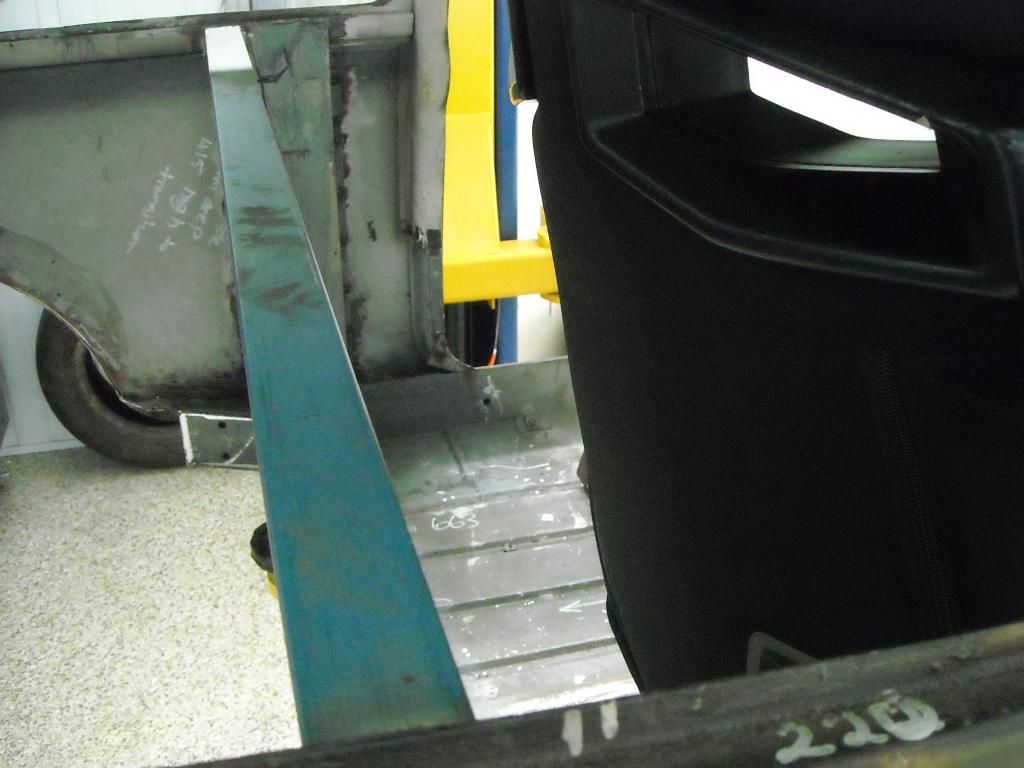
Mounting the seats I tested their extent of travel along the seat rails. While the limit of travel of the rails was achieved in both directions, the angle of seat recline was limited by the rollcage/firewall location. Testing showed that we could get three clicks of recline from the vertical position, which should be enough for most drivers I would think.

Seats in position - Sparco 333's, a really nice seat:
Image

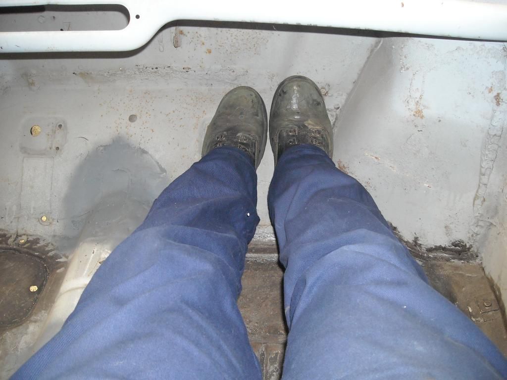
Enough room???
Image

Me, in the seat - I'm 5'8", Justin is a little taller, but my legs are straight and I can just touch the firewall even with boots on:
Image

Seat back travel - upright position with the seat in its rearmost position on the seat rails:
Image

2nd position - preferred by me as I like an upright position:
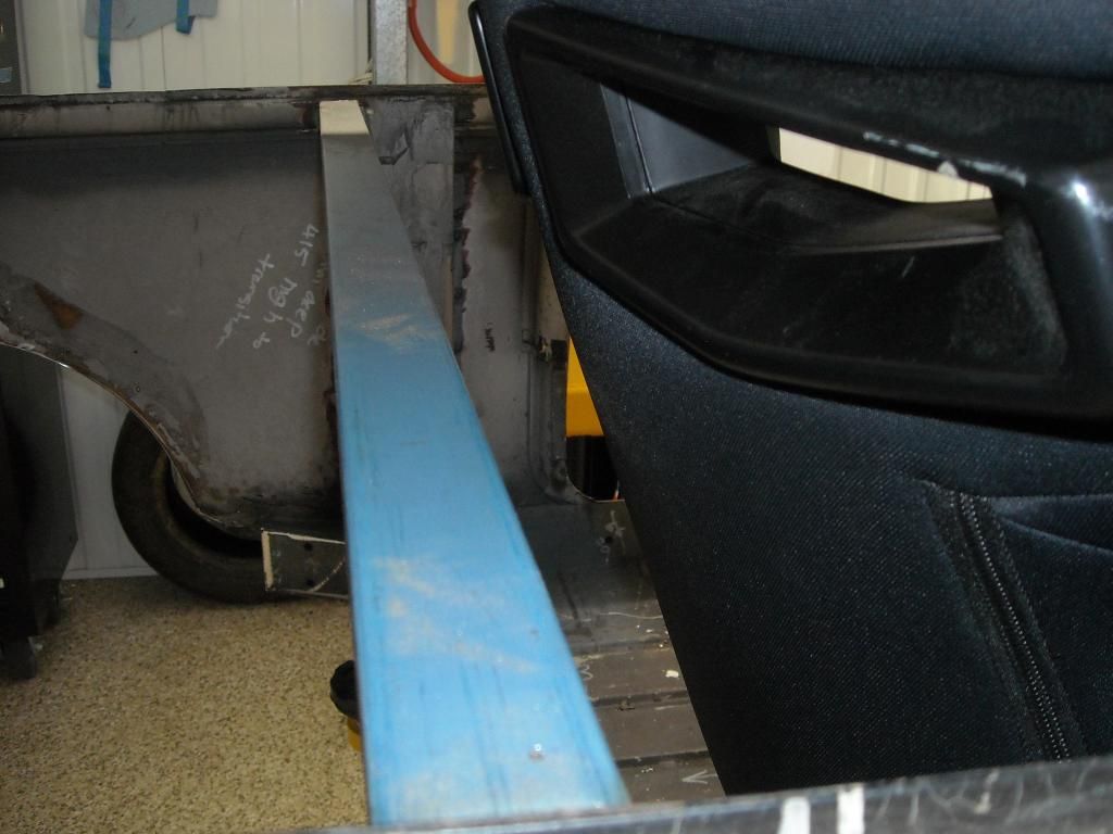
Image

3rd position with the seat at its rearmost travel - the rollcage diagonal brace may interfere slightly here:
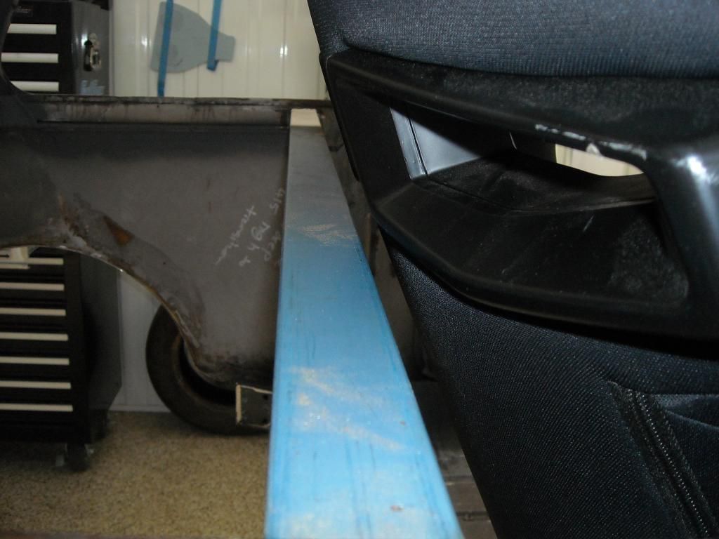
Image

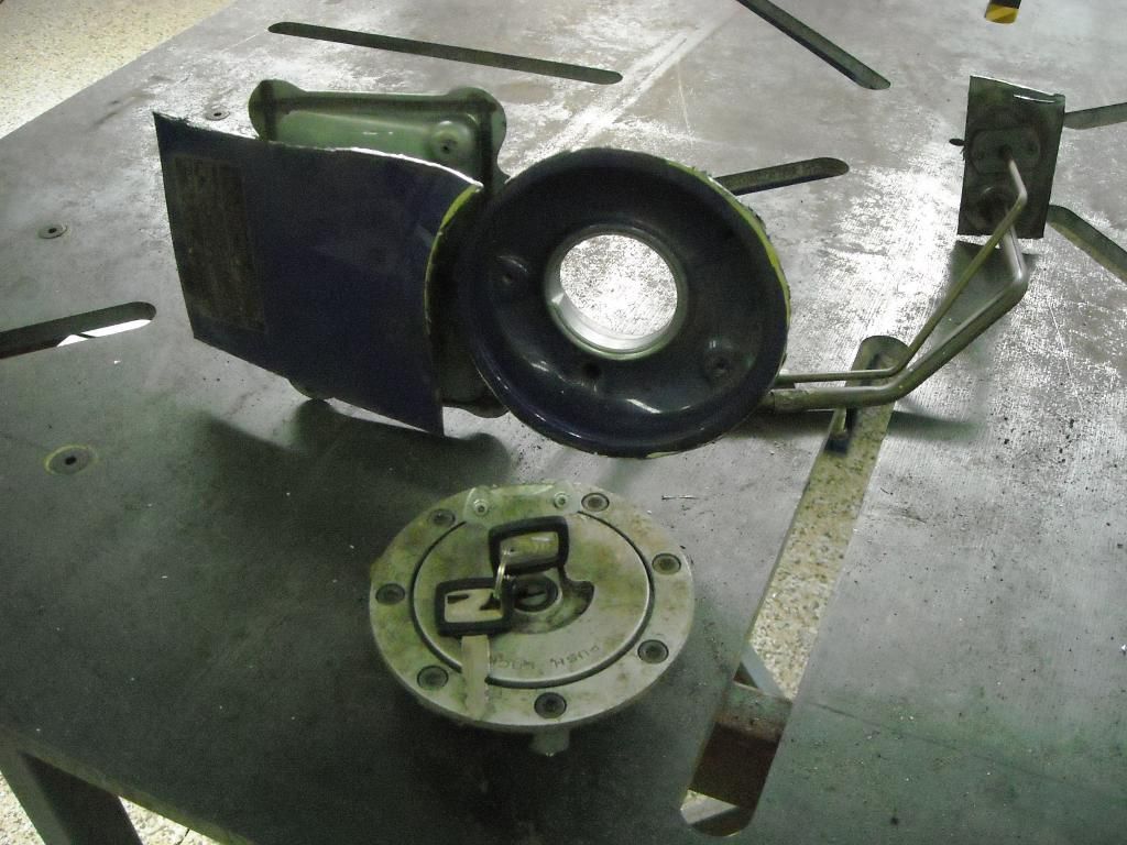
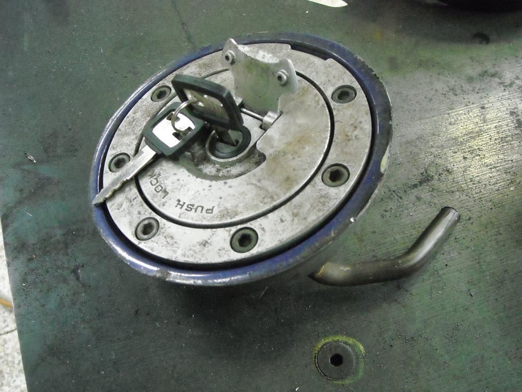
Seats done - check! Next I decided to take a detour from doing the structural stuff (albeit almost completed now) and move onto doing something a bit more creative (the whole project is 'creative' - what you talkin' about Willis??). I decided to tackle the fuel filler location just for some razzle dazzle and send Justin some pics of something other than structure. Since the fuel tank is to be located in the front, a fill point had to be fabricated at some point. Justin wanted it external, and on the drivers side - good choice. I suggested a motorcyle-style filler, similar to El Gato - inset into the guard. I sent Justin some pics off the Interweb of what I was thinking and he said how visionary and creative I was and to go ahead! :roll: So, off to the motorcycle wreckers and I grabbed this - a dented fuel tank from a late model CBR600 (in keeping with the Honda theme!!). I took it around to a mates Locksmith shop and got the lock picked and three keys cut, as it didnt come with any keys - total outlay was $85 for the day. Here it is with the filler cutout:
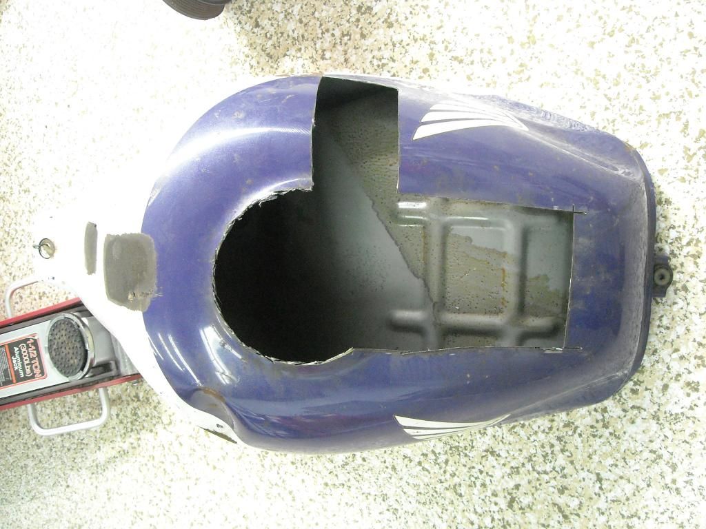
Image

Said filler assembly:
Image

Trimmed to size and read to got in:
Image

The final position of the filler was determined by the tank shape, guard profile, fill height of the tank, and the alignment of Venus in the house of Gemini:
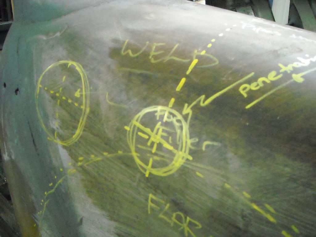
Image

It couldnt be too high, as the guard profile was too rounded, and it couldnt be too low as it would not allow enough fall to fill the tank safely. It also had to align up with the area I had chosen inside the (old) engine bay for the entry point. Ahh yes, just right (top hole as 'X' marks the spot:
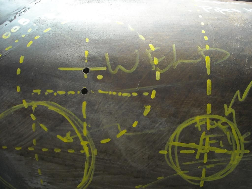
Image

Then out with a whopping big holesaw and cut the guard out (what have I done, no going back now!!):
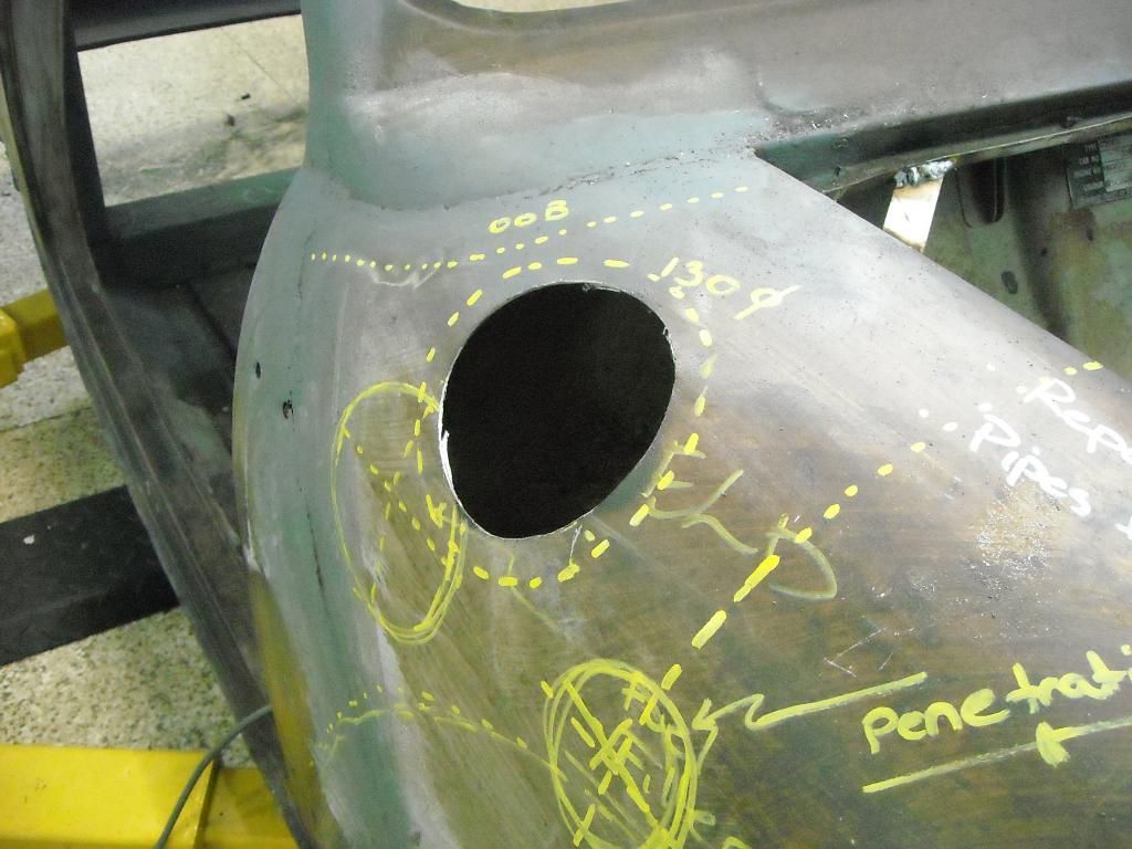
Image

Then, make up the surround to fit around the filler neck - a kind of collar if you like:
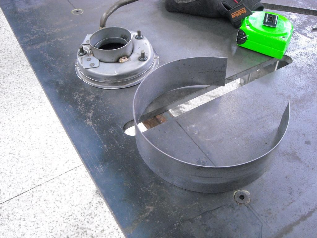
Image

Weld it on and clean it up. Filler neck also done:
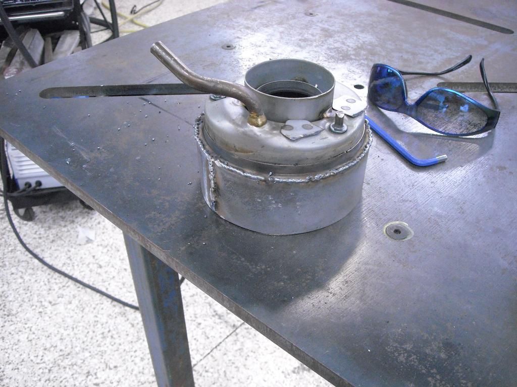
Image

And then insert it into the big whopping hole, hoping it all is roughly the same size (of course it is, its engineered after all!):
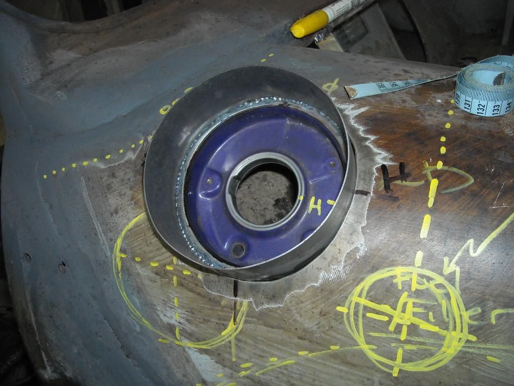
Image

Happy with the fit and position, tack it in place. Make sure the filler 'lid' swings the right way:
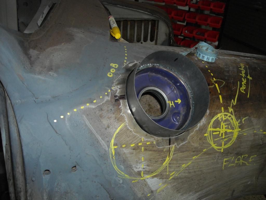
Image

Weld it in from underneath where you can, and from the top where you cant:
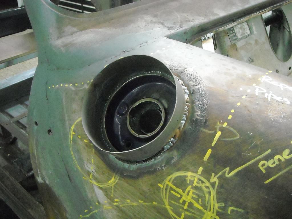
Image

Cut away the excess collar, and clean up with the flap disc. How's that for razzle dazzle??? Notice the lid swings to the front - this is so that if Justin forgets to lcok it securely, the onrushing air stream will hold the lid down and not flick it open:
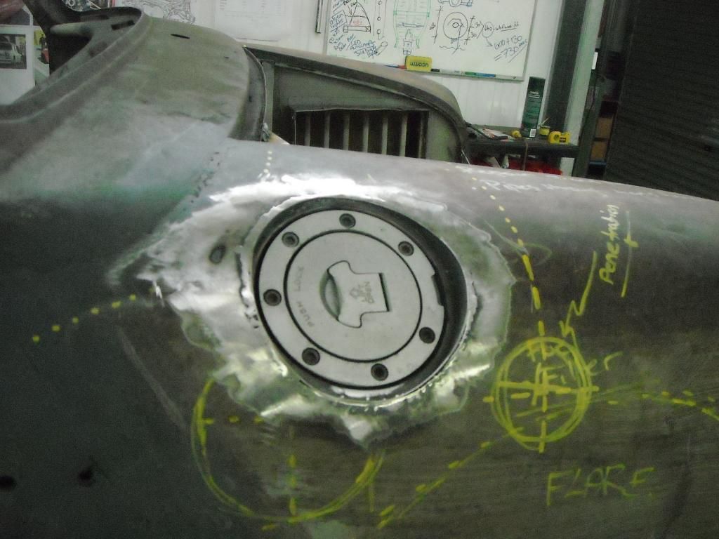
Image

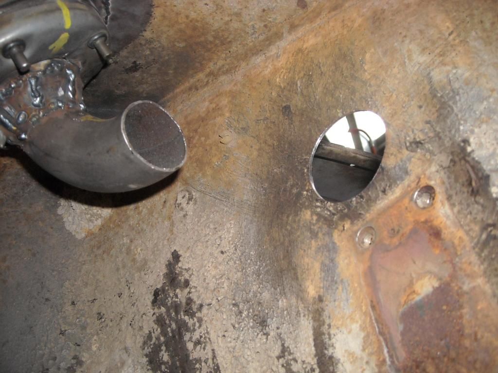
Prior to welding in, I welded on an elbow to the underside fill neck to allow the flow to turn 90-degress. Then it would turn another 90-degrees into the (old) engine bay. Here is the 90-degree bend underneath the guard. You can see the entry point into the engine bay:
Image

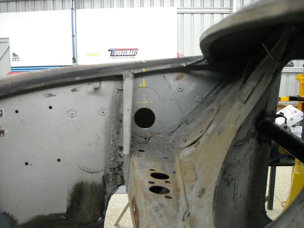
And, perfect alignment with where I wanted the fill-pipe to come in. From here it will do another 90-degree bend into the tank. It should fill just fine, albeit a little slow:
Image

More soon.

Cheers,
Tricky

_________________
"Not Speeding Officer..........Qualifying"


Top
 Profile  
 
PostPosted: Sun Sep 14, 2014 10:18 am 
Offline
1098cc
1098cc
User avatar

Joined: Thu Sep 30, 2004 3:12 pm
Posts: 1461
Location: Brisbane
Tricky you can buy those fuel filler caps new from some where but they're still mighty expensive! Probably cheaper to buy it the way you have...
I've still got the box at home I'll try and get a name off it

Image

Edit : definitely cheaper to do it your way, I'm pretty sure the one on mine was a few hundred

_________________
If you want more inches, stroke it
Life's a garden.... Dig It!
http://www.ausmini.com/forums/viewtopic.php?t=20746


Top
 Profile  
 
PostPosted: Sun Sep 14, 2014 7:44 pm 
Offline
1275cc
1275cc
User avatar

Joined: Thu May 24, 2007 7:19 pm
Posts: 5370
Location: Yandina,Sunshine Coast,QLD
Constructive critism: I don't like the recess lip around the filler, was it not possiable to mount a filler (maybe a different one) to the top of the guard or through the bonnet like a Ford "shaker bonnet scoop" :?: . IMO with everything else being so smoothed out on the body will a lip like that seem out of place?
Apart from that it's all done well and the build is great to watch.

_________________
Respect mine and I'll respect yours.


Top
 Profile  
 
PostPosted: Mon Sep 15, 2014 1:53 pm 
Offline
1275cc
1275cc
User avatar

Joined: Thu Jun 03, 2004 2:56 pm
Posts: 3981
Location: Brisbane
Nice. Unconventional, some might say "Tricky".

_________________
But he's thriving and striving and hugging the turns.


Top
 Profile  
 
PostPosted: Wed Sep 24, 2014 12:14 pm 
Offline
1275cc
1275cc
User avatar

Joined: Fri Jun 17, 2005 10:31 am
Posts: 3183
Location: Burpengary, Queensland - Home of Tricky Performance Engineering
You always had a way with words JC......!!! :shock:

_________________
"Not Speeding Officer..........Qualifying"


Top
 Profile  
 
PostPosted: Mon Sep 29, 2014 8:22 pm 
Offline
848cc
848cc

Joined: Thu Jun 26, 2014 8:45 pm
Posts: 98
Well I had the pleasure of meeting with Tricky on the weekend and casting an eye over the little beast, impressive amount of cleaver thinking and work has gone into this, it will be unbelievable on the road I am sure. Thanks for the inspiration and your time, hopefully in about six months my own little build will begin


Top
 Profile  
 
Display posts from previous:  Sort by  
Post new topic Reply to topic  [ 105 posts ]  Go to page Previous  1 ... 3, 4, 5, 6, 7  Next

All times are UTC + 10 hours


Who is online

Users browsing this forum: No registered users and 5 guests


You cannot post new topics in this forum
You cannot reply to topics in this forum
You cannot edit your posts in this forum
You cannot delete your posts in this forum
You cannot post attachments in this forum

Jump to:  

© 2016 Ausmini. All garage work involves equal measures of enthusiasm, ingenuity and a fair degree of irresponsibility.