Evening Viewers,
Ross - thanks very much mate. Glad you approve.
Howdy Pete - Well now you know where all the action is. I am just one of many doing a conversion, and a lot of them are top-shelf endeavours as well. But, sincerely, thanks very much for your kind and thoughtful words, its been a long journey aye, but the end is in sight now.
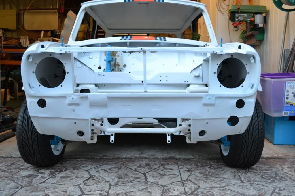
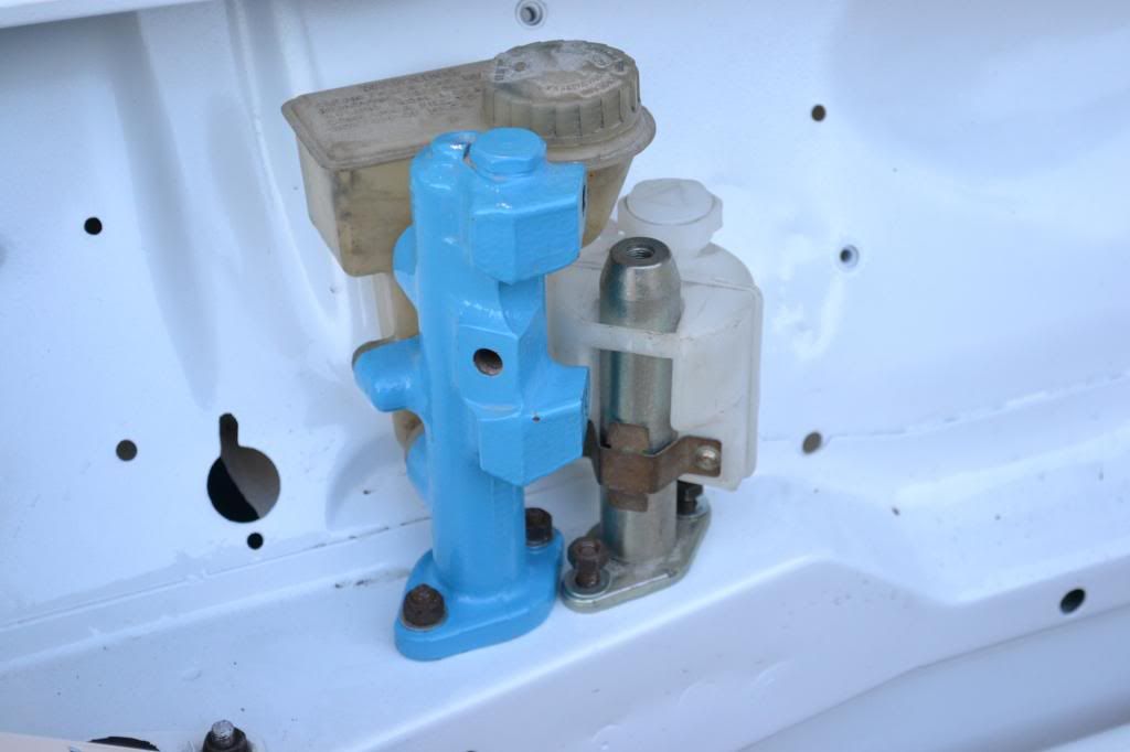
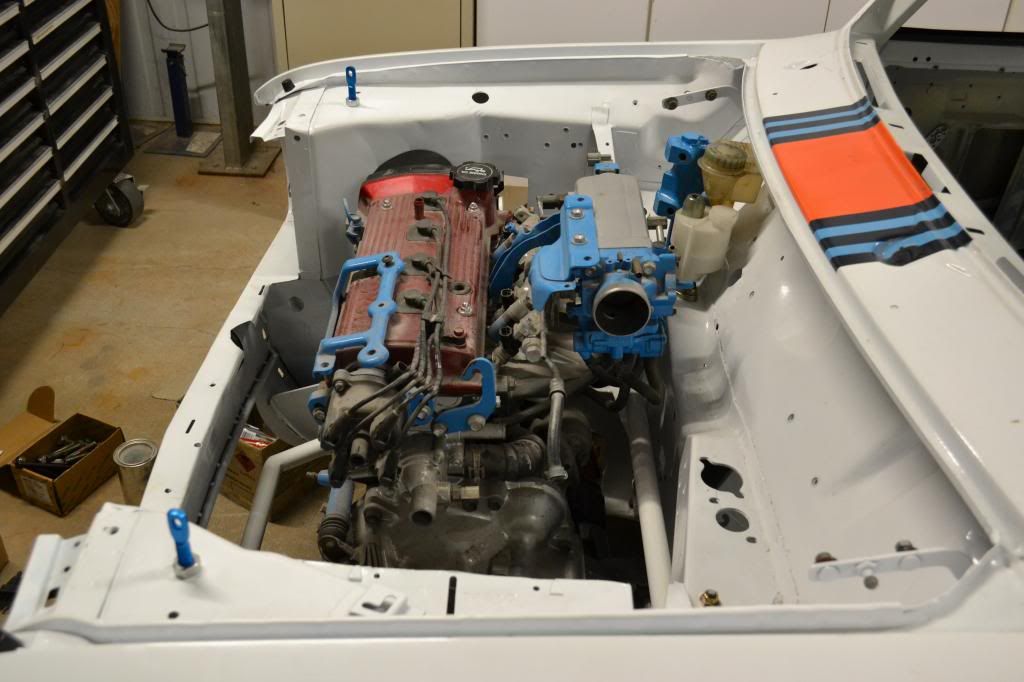
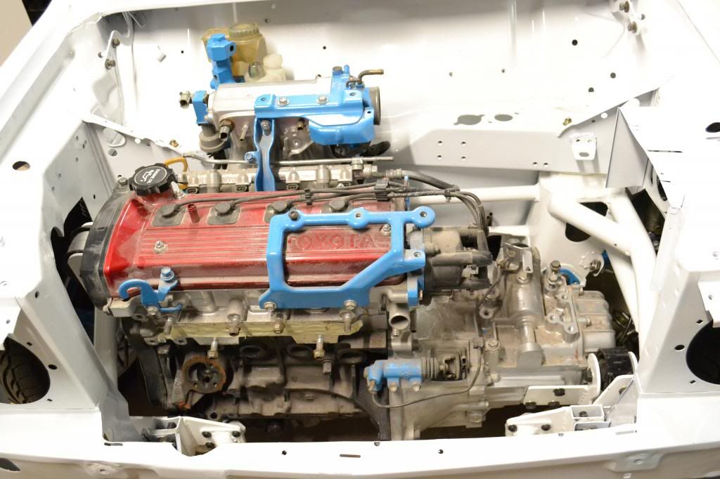
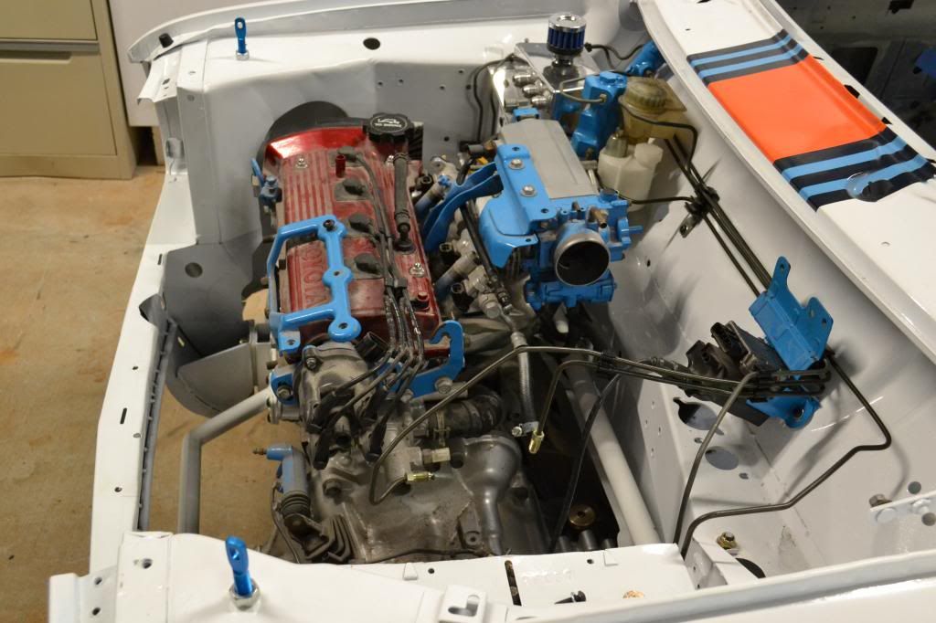
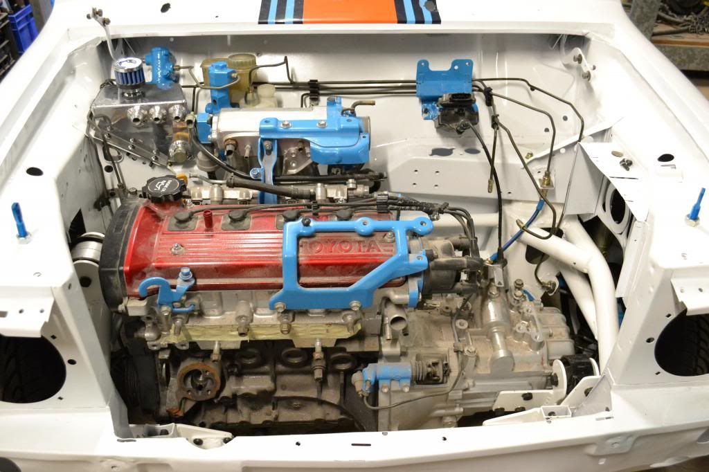
A bit of an update. Spend the day in the engine compartment picking up where we left off. Installed the brake lines, which werent that hard because they were all pre-bent. The hard part was doing the final connections to the different fittings - especially the front brake lines. Also installed the accelerator cable, brake proportioning valve, as it was behind the oil catch-can, and then the oil catch-can itself.
Had to do some serious polishing on the catch-can, as it had many years of fingerprints, grime, dust etc. It can up just fine. Also polished the radiator overflow, but will install that tomorrow as the bracket holding it on needs polishing too. This bracket sits off the mount that holds the coilpack and ignitor, which we installed as well.
Then I decided to have some fun!! Because I am running a Digidash from ETB Instruments, which has a digital speedo, it uses a Hall effect sensor to pick up magnetic impulses that tell it how fast the vehicle is moving. Now these magnets could be mounted anywhere on anything rotating at the same proportional speed as the car - like a tailshaft or driveshaft.
But, I wanted to do something a bit more engineered and I wanted to use the original speedo cable drive out of the gearbox. So, this would require some thinking and some machining (I love machining!!). This is a job I have put off until the car was going back together, so here it comes.
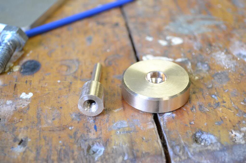
I started off by buying a 16mm x 5mm bearing from BSC - this would form the basis of our speedo drive, as it fitted inside the speedo cable take-off housing. Next was to turn down some metal to make an arbor - luckily I had some brass stock leftover from turning some lamps necks for the wife (why brass, does not rust and non-magnetically conductive). So, I turned down in the lathe some brass to act as an arbor - the dimensions had to be spot on as we wanted an interference fit into the bearing ID, which was 5.0mm, so we turned the brass down the shaft to 5.10mm. The oustide diameter of the body was 12mm, which fits through the screw collar that would normally hold the speedo cable in place. Then we drilled andf tapped a 6mm thread into the body.
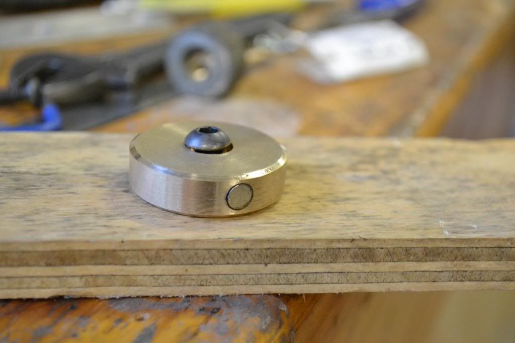
Next, we machined a flywheel, which would house the two magnets which give the impulses to the Hall effect sensor - 35mm diameter and with a 6.5mm hole through the center, and countersunk:
Then we drillled into the outer face of the flywheel 6mm holes for the magnets, and epoxied them in - they must be perfectly 180 degrees apart:
Then we assembled the whole lot together, not forgetting to include to collar into the mix. Press fit the bearing into place, and then Loctited the 6mm socket head bolt through the flywheel and into the arbor:
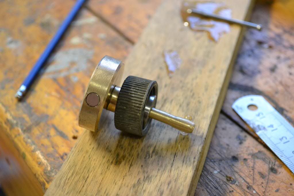
Then because it was too hard to machine a keyway into the arbor shaft (the original speedo cable has its keyway 'pinched' into it by a special machine), I decided that some epoxy on the end should secure it enough to hold it in place. Remember, it does have to do anything but spin inside the bearing, only having to overcome its own rotational inertia - so hopefully the epoxy will be enough. And then we install it, by simply screwing down the original collar:
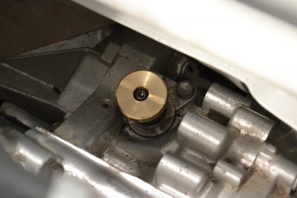
Tomorrow we shall make up a bracket for the Hall effect sensor - it must have an airgap not exceding 1.0mm. Luckily the runout on the assembly was only 0.2mm which was acceptable.
Also tomorrow, more polishing and more installing - stay tuned.
Cheers,
Tricky